Protective circuit for reducing electrical disturbances during operation of a DC motor

a protection circuit and dc motor technology, applied in the direction of commutation monitoring, multiple dynamo-electric motor speed regulation, dynamo-motor starters, etc., can solve the problems of only limited utility, complicated use, and electrical interference or disturbances that affect the control of dc motors, so as to reduce electrical disturbances and increase the resistance of the series transistor

Inactive Publication Date: 2006-10-10
EBM PAPST ST GEORGEN & -
View PDF9 Cites 26 Cited by
  • Summary
  • Abstract
  • Description
  • Claims
  • Application Information

AI Technical Summary

Benefits of technology

[0004]It is an object of the present invention to provide an improved protective circuit for reducing electrical disturbances during operation of a DC motor. This object is achieved by a protective circuit which includes a series transistor 62 arranged in a supply lead from a DC voltage source 12 to the DC motor, an auxiliary voltage source 52, associated with that series transistor, applying a substantially constant auxiliary voltage which is configured to make the series transistor 62 fully conductive when a supply voltage furnished by the DC voltage source is substantially free of electrical interference, and an analyzer circuit for analyzing the supply voltage, the analyzer circuit being configured, upon the occurrence of electrical interference in the supply voltage, to increase the resistance of the series transistor 62 correspondingly, in order to reduce the influence of that electrical interference on the operation of the DC motor.
[0006]According to a preferred embodiment of the invention, the power controller is implemented as a series transistor. The drive circuit causes the series transistor to be fully conductive when the input voltage is substantially free of electrical interference. As a result, the input voltage is delivered to the DC motor, substantially without losses, as the supply voltage. Upon the occurrence of electrical interference in the form of transient pulses, the drive circuit causes the series transistor to limit the amplitude, of the supply voltage generated by the protective circuit, to a predetermined value.
[0008]The present invention makes possible a reduction in electrical interference during the operation of DC motors using a comparatively simple and low-cost protective circuit. The invention is not limited to a specific type of motor.

Problems solved by technology

During the operation of DC motors, the occurrence of electrical interference or disturbances constitutes a problem.
In particular, the occurrence of electrical interference, in control circuits that are configured for electronic commutation of currents flowing in a DC motor, can negatively affect control of the DC motor.
The necessary size, restricted working temperature, and limited service life of LC filters or filter capacitors, however, makes them complicated to use and of only limited utility.
The use of varistors is complex and cost-intensive because of the varistor dimensions that are required.

Method used


Image

  • Protective circuit for reducing electrical disturbances during operation of a DC motor
  • Protective circuit for reducing electrical disturbances during operation of a DC motor
  • Protective circuit for reducing electrical disturbances during operation of a DC motor

Examples


first embodiment

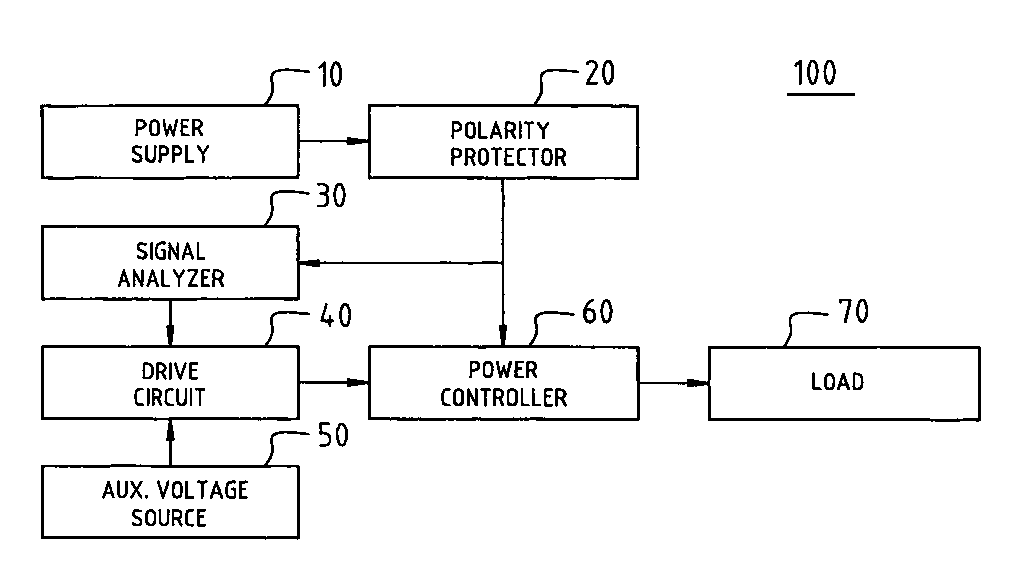
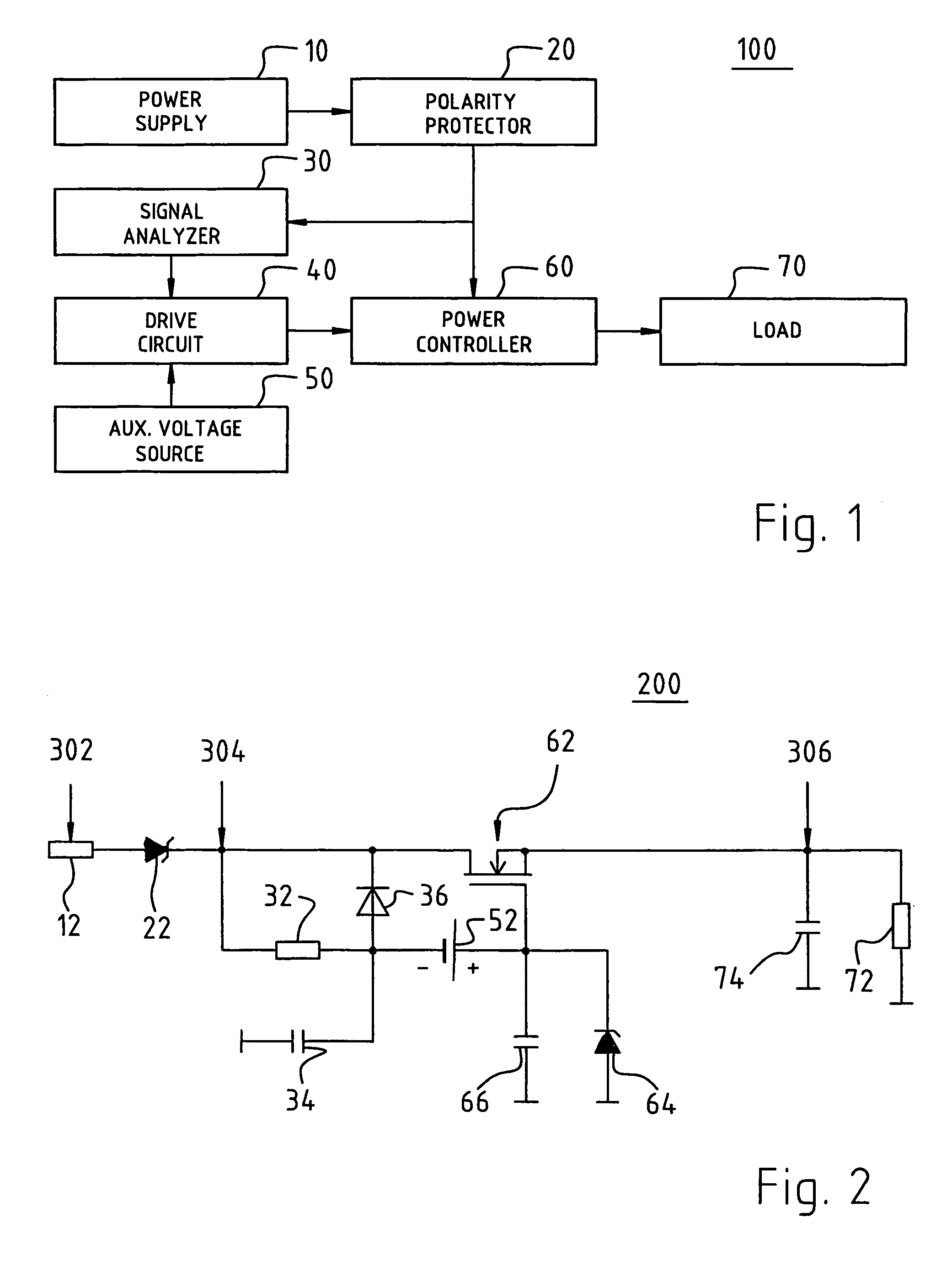
[0021]FIG. 2 is a highly simplified circuit diagram of an illustrative protective circuit 200 for reducing electrical interference, according to the present invention. The illustrative protective circuit 200 comprises a supply voltage source 12 and a load 72, shown schematically as a resistor. A positive line of supply voltage source 12 is connected to the anode side of a diode 22. The output signal of diode 22 is delivered from the cathode side of diode 22 through a resistor 32 to the negative pole of an auxiliary voltage source 52. The output signal of diode 22 is furthermore delivered to the cathode side of a diode 36 and to the drain region of a series transistor (MOSFET) 62. The anode side of diode 36 and the negative pole of auxiliary voltage source 52 are connected to ground via a storage capacitor 34. The positive pole of the auxiliary voltage source is connected to the gate of series transistor 62. The positive pole of auxiliary voltage source 52 is furthermore connected to...

second embodiment

[0032]FIG. 4 is a highly simplified circuit diagram of an illustrative protective circuit 400 for reducing electrical interference, according to the present invention. In protective circuit 400, a diode circuit in which, for example, four diodes 54, 55, 56, and 57 are connected in series is arranged between capacitor 34 and the gate of series transistor 62. A resistor is arranged, in parallel with the four series-connected diodes 54, 55, 56, and 57, between resistor 32 and the gate of series transistor 62. Protective circuit 400 furthermore comprises a voltage source 82 that is connected via a current limiting resistor 84 to the anode side of a diode 86. The cathode side of diode 86 is connected on the one hand via a capacitor 87 to ground, and on the other hand via a resistor 88 to the cathode side of Zener diode 64. The circuit arrangement otherwise corresponds to the one shown in FIG. 2.

[0033]In protective circuit 400, the parallel circuit of the four diodes 54, 55, 56 and 57 wit...


PUM


Abstract

A protective circuit, for reducing electrical disturbances or interference during operation of a DC motor, features a series transistor (62) arranged in a supply lead from a DC voltage source (12) to a DC motor; an auxiliary voltage source (52), associated with that series transistor, having a substantially constant auxiliary voltage which is configured to make the series transistor (62) fully conductive when a supply voltage furnished by the DC voltage source is substantially free of electrical interference; and an analyzer circuit (32, 34, 36) for analyzing the supply voltage, which analyzer circuit is configured, upon the occurrence of electrical interference in the supply voltage, to increase the resistance of the series transistor (62) correspondingly, in order to reduce the influence of that electrical interference on the operation of the DC motor.

Description

FIELD OF THE INVENTION[0001]The present invention is directed to a protective circuit for reducing electrical disturbances during operation of a DC motor, and to a DC motor having a corresponding protective circuit.BACKGROUND[0002]During the operation of DC motors, the occurrence of electrical interference or disturbances constitutes a problem. In particular, the occurrence of electrical interference, in control circuits that are configured for electronic commutation of currents flowing in a DC motor, can negatively affect control of the DC motor. Such electrical disturbances or interference encompasses both high-energy transient pulses and low-voltage interference in the frequency range from 50 Hz to 20 kHz, with amplitudes of 6 V peak-to-peak.[0003]Protective circuits used in the existing art encompass varistors and LC filters or filter capacitors to protect DC motors from electrical interference. The varistors serve to absorb the high-energy transient pulses, and the LC filters o...

Claims


Application Information

Patent Timeline
Patent Type & Authority Patents(United States)
IPC IPC(8): H02P5/46H02H7/08H02P6/12H02P7/18H02P7/28H03K17/16
CPCH02P7/28H03K17/165
Inventor DORNHOF, KONSTANTIN
Owner EBM PAPST ST GEORGEN & -
Why Eureka
Try Eureka