Monitoring and correction of geometric distortion in projected displays

a technology of projection display and monitor, which is applied in the direction of projection device, television system, pulse technique, etc., can solve the problems of display miscalibration, interrupting display use, and projector system subject to display

Inactive Publication Date: 2006-10-10
UNIV OF KENTUCKY RES FOUND
View PDF4 Cites 38 Cited by
  • Summary
  • Abstract
  • Description
  • Claims
  • Application Information

AI Technical Summary

Benefits of technology

[0009](a) Ease of operability—The invention provides an ability to automatically correct distortion / keystoning experienced by front-projected displays and make associated adjustments without operator intervention, allowing the party presenting the display full opportunity to focus on the presentation material, or in the case of fully-automated presentation / entertainment, fewer (if any) display distractions will need maintenance operator intervention.

Problems solved by technology

Most, if not all, light projector systems are subject to display distortion, whether caused by perturbations of an electronic and / or mechanical nature (e.g., vibrations common to most viewing environments, such as ventilation system operation, doors closing, and so on), resulting in display mis-calibration.
Although commodity solutions exist for removing this distortion, they involve iterative, menu-driven user interaction or physical alignment of the projector, and in either case interrupt the use of the display.

Method used


Image

  • Monitoring and correction of geometric distortion in projected displays
  • Monitoring and correction of geometric distortion in projected displays
  • Monitoring and correction of geometric distortion in projected displays

Examples


Embodiment Construction

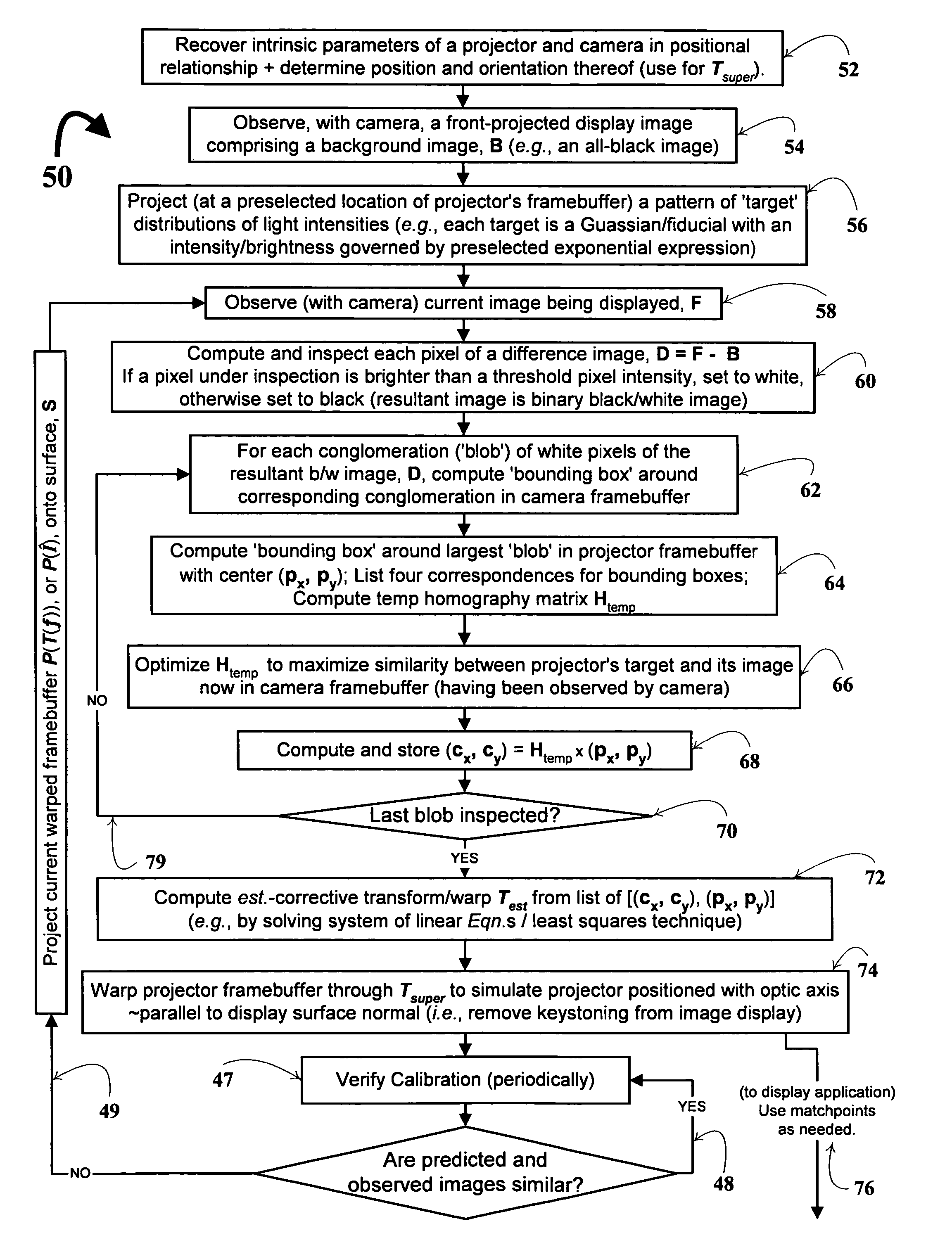
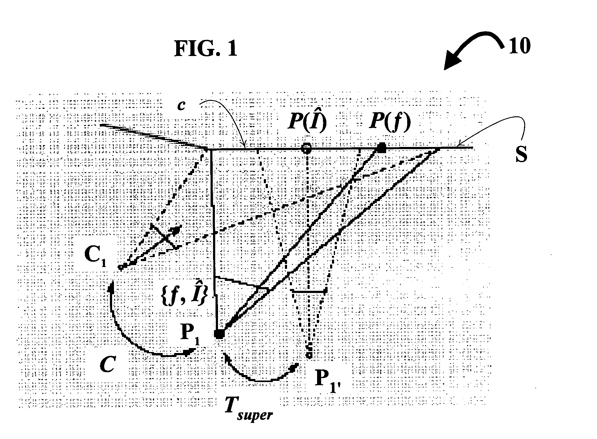
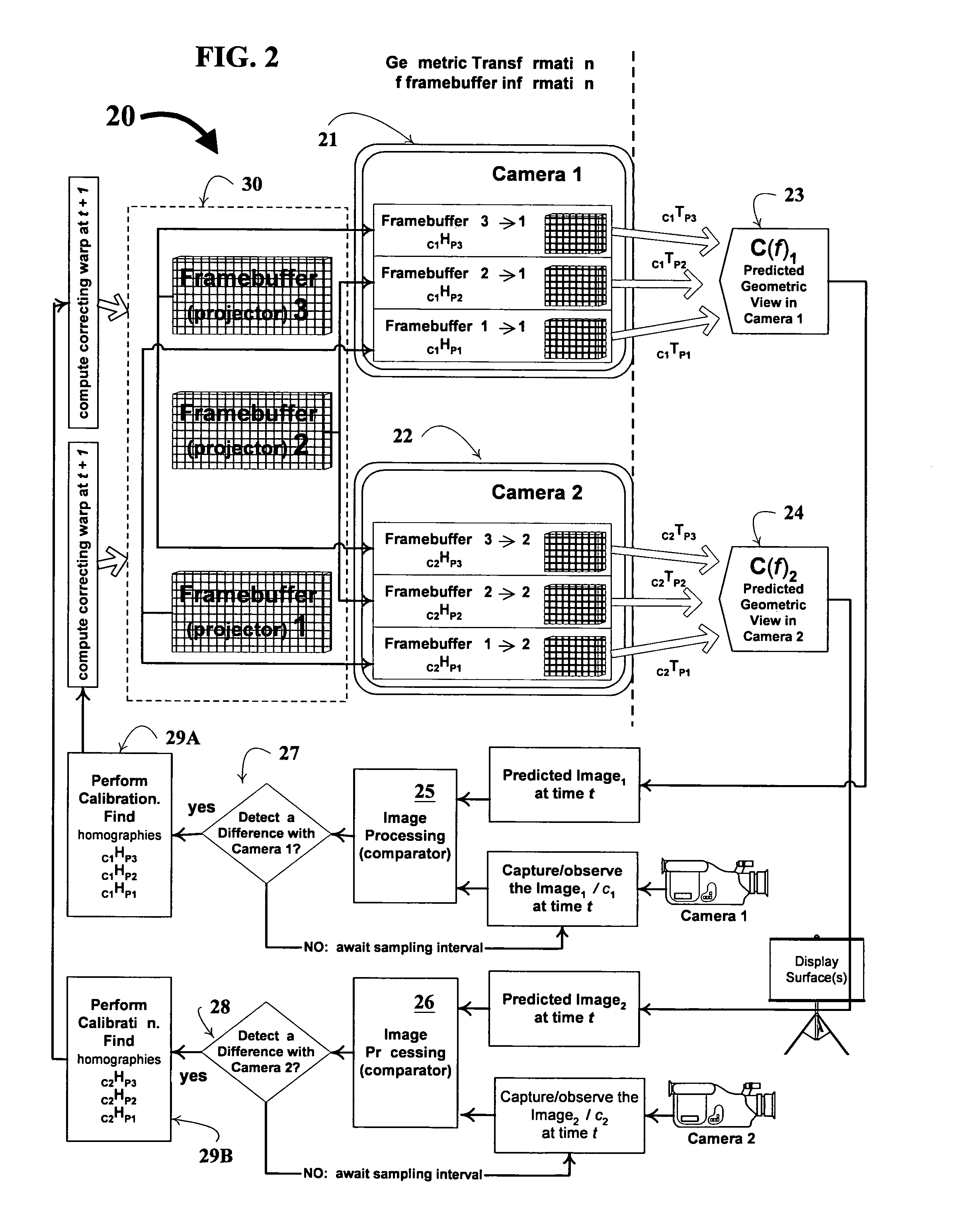
[0017]In connection with discussing the features in FIGS. 1–2, occasional reference will be made back-and-forth to other of the figures, especially, FIGS. 3–4 which detail core, as well as further unique and distinguishing features of technique of the invention 50—and further providing a pictorial demonstration of the flexibility of design of applicant's invention. As one can appreciate, the configuration of the simplified projector-camera pair system 10 in FIG. 1 is suitable for a wide variety of display environments.

[0018]FIG. 1 depicts a projector-camera system 10, having for example, at least one projector at position P1. P1′ designates a simulated position for projector P1 once the projector's framebuffer is warped, so that the projector's optic axis is ˜parallel to the display surface normal, according to the invention. While only one projector is projecting to contribute to the display of surface S, additional projectors may be included; at least one camera C1 is also depicte...


PUM


Abstract

A technique, and associated system and computer executable program code on a computer readable storage medium, for automatically correcting distortion of a front-projected display under observation by at least one camera. The technique may be employed in a myriad of front-projected display environments, e.g., single or multiple projectors and cameras are used. The technique includes: observing a first image, projected from at least one projector, comprising at least one target distribution of light intensities; for each conglomeration of white pixels of a difference image, compute a bounding box comprising a corresponding conglomeration of pixels in a framebuffer information of the camera, compute a bounding box comprising a corresponding conglomeration of pixels in a framebuffer information of the projector, compute an initial homography matrix, Htemp, mapping pixels of the projector's bounding box to those of the camera's bounding box, optimize the initial homography matrix, compute a central location, (Cx, Cy), of the camera's bounding box using the initial homography matrix; and using a plurality of correspondence values comprising the correspondence, compute a corrective transform to aid in the automatic correcting of the display.

Description

[0001]The applicants hereof filed pending U.S. patent application Ser. No. 10 / 315,377 entitled Dynamic Shadow Removal from Front Projection Displays on Dec. 9, 2002; subject matter of application Ser. No. 10 / 315,377 and that of the instant application, as well as the pending provisional application to which this application claims benefit, was all commonly-owned by the assignee hereof at the time of invention.[0002]This application claims the benefit of pending U.S. provisional patent application No. 60 / 430,575 filed Dec. 3, 2002 for the applicants on behalf of the assignee hereof. The invention disclosed herein was made with United States government support awarded by the following agency: National Science Foundation, under contract number NSF-4-62699. Accordingly, the U.S. Government has certain rights in this invention.BACKGROUND OF THE INVENTION[0003]In general, the present invention relates to light projector systems used for information display on a surface. Most, if not all, ...

Claims


Application Information

Patent Timeline
Patent Type & Authority Patents(United States)
IPC IPC(8): H04N17/00H04N3/26H04N5/74H04N9/31
CPCH04N5/74H04N9/3185H04N9/3194H04N9/3197
Inventor JAYNES, CHRISTOPHER O.STEELE, ROBERT M.
Owner UNIV OF KENTUCKY RES FOUND
Why Eureka
Try Eureka