Contrast chiral nematic liquid crystal displays

a liquid crystal display and contrast technology, applied in the field of display sheets, can solve the problems of loss of performance, change in reflected color, and harmful uv radiation to liquid crystals, and achieve the effect of improving contrast and purity of reflected color

Active Publication Date: 2006-10-10
HKC CORP LTD
View PDF25 Cites 17 Cited by
  • Summary
  • Abstract
  • Description
  • Claims
  • Application Information

AI Technical Summary

Benefits of technology

[0009]The present invention includes several advantages, not all of which are incorporated in a single embodiment. The displays based on chiral nematic materials of the invention demonstrate substantial improvement in the contrast and in the purity of its reflected color.

Problems solved by technology

While the emulsion methods are straightforward to implement, droplet size distributions tend to be broad resulting in a loss in performance.
Although phase separation methods produce dispersed droplets having more uniform size distributions, there are numerous problems with this approach.
Furthermore, it is also known that UV radiation is harmful to liquid crystals.
Specifically, exposure to UV radiation can lead to decomposition of the chrial dopant in a cholesteric liquid crystal mixture, resulting in a change in the reflected color.
The use of organic solvents may also be objectionable in certain manufacturing environments.
It is well known that the shape of the droplet causes reflections in the planar state at wavelengths lower than the main band, giving rise to a loss in color purity.
The process suffers from the disadvantage that numerous coloring agents, such as color dyes, are extremely sensitive to UV radiation and the presence of reactive free radicals, produced by UV irradiation.

Method used


Image

  • Contrast chiral nematic liquid crystal displays
  • Contrast chiral nematic liquid crystal displays
  • Contrast chiral nematic liquid crystal displays

Examples


example 1

Control

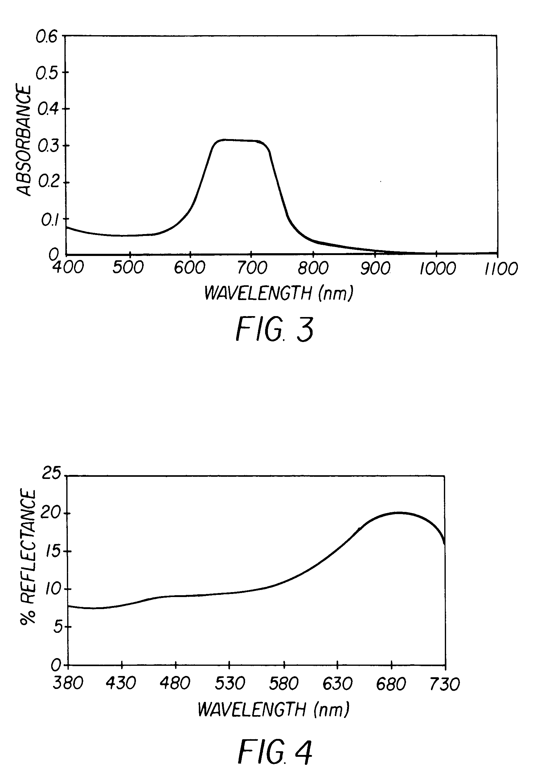
[0068]This example illustrates the effect of the shape of the coated droplet on the spectrum of a chiral nematic liquid crystal (N*LC) formulation. FIG. 3 shows the spectrum of a red reflecting chiral nematic formulation between glass slides. The material was prepared by adding the appropriate amount of a high twist chiral dopant to the nematic host mixture BL087 obtained from Merck, Darmstadt, Germany. Although the y-axis of FIG. 3 says ‘absorbance’, it should be noted that there is no light absorption by these materials. At the reflecting wavelength, theoretically half the incident light is reflected and the other half is transmitted. Therefore, the spectrophotometer should measure an “absorbance” of 0.3 where “absorbance” is simply log10 (1 / T); T being the transmittance of the sample. Since half the light is transmitted, T should theoretically be 0.5 and log10 (2) should be approximately 0.3. FIG. 3 shows that the maximum “absorbance” of the sample is indeed close to 0.3.

[...

example 2

Invention

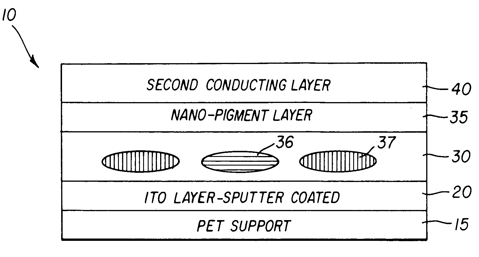
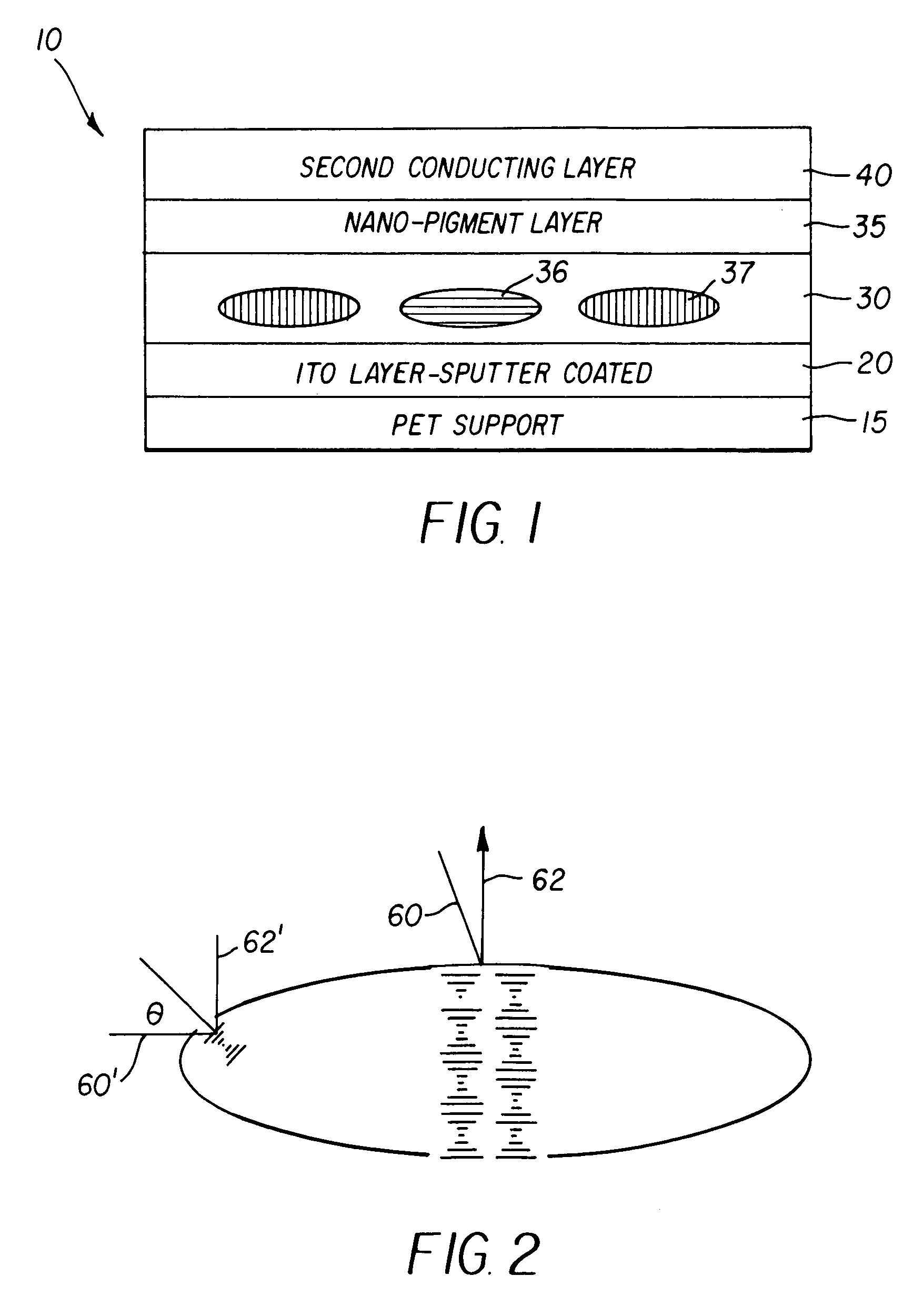
[0073]A chiral nematic composition with center wavelength of reflection at 590 nm (measured with the sample between glass slides) was prepared by adding the appropriate amount of a high-twist chiral dopant to the nematic host mixture BL087 obtained from Merck, Darmstadt, Germany. A second chiral nematic composition was prepared in the same manner but also contained 0.25% of the oil soluble blue absorber dye Neopen 075 from BASF Corporation.

[0074]Dispersions of the chiral nematic compositions were prepared as follows. To 200 grams of distilled water was added 3.3 grams of Ludox® colloidal silica suspension and 6.9 grams of a 10% w / w aqueous solution of a copolymer of methylaminoethanol and adipic acid. To this was added 90 grams of any one of the chiral nematic compositions prepared above. The mixture was stirred using a Silverson ®mixer at 5000 rpm. It was then passed twice through a Microfluidizer® at 3000 psi. Two hundred and eighty grams of the resulting dispersion was m...


PUM

PropertyMeasurementUnit
thicknessaaaaaaaaaa
sizeaaaaaaaaaa
diameteraaaaaaaaaa

Abstract

The present invention relates to a bistable polymer dispersed liquid crystal display comprising a support, at least one patterned first conductor layer having thereon at least one dried imaging layer comprising a substantial monolayer of isolated domains of liquid crystal material dispersed in a continuous polymer matrix, wherein said dried imaging layer further comprises at least one absorber colorant, and wherein said isolated domains have a size distribution such that the coefficient of variation (cv) is less than 0.35.

Description

FIELD OF THE INVENTION[0001]The present invention relates to a display sheet having a chiral nematic liquid crystal layer containing a colorant to provide a relatively lighter (brighter) state and a relatively darker state.BACKGROUND OF THE INVENTION[0002]There are two main methods for fabricating polymer dispersed liquid crystal devices, also referred to herein as PDLC devices: emulsion methods and phase separation methods. Emulsion methods have been described in U.S. Pat. Nos. 4,435,047 and 5,363,482. The liquid crystal is mixed with an aqueous solution containing binder. The liquid crystal is insoluble in the continuous phase and an oil-in-water emulsion is formed when the composition is passed through a suitable shearing device, such as a homogenizer. The emulsion is coated on a conductive surface and the water allowed to evaporate. A second conductive surface may then be placed on top of the emulsion layer by lamination, vacuum deposition, or screen printing to form a device. W...

Claims


Application Information

Patent Timeline
Patent Type & Authority Patents(United States)
IPC IPC(8): G02F1/1333G02F1/1334G02F1/137
CPCG02F1/1334G02F1/13718G02F1/13725G02F2001/13775G02F1/13775
Inventor CHARI, KRISHNANRANKIN, JR., CHARLES M.WELTER, THOMAS R.
Owner HKC CORP LTD
Why Eureka
Try Eureka