Automated wear leveling in non-volatile storage systems

a non-volatile storage system and wear leveling technology, applied in the direction of micro-instruction address formation, memory address/allocation/relocation, instruments, etc., can solve the problems of significant performance degradation, loss of use, and adverse effects on users of flash memory systems, so as to achieve significant reduction of performance penalties for performing wear leveling

Active Publication Date: 2006-10-10
SANDISK TECH LLC
View PDF109 Cites 238 Cited by
  • Summary
  • Abstract
  • Description
  • Claims
  • Application Information

AI Technical Summary

Benefits of technology

[0013]By moving relatively small amounts of data using a gradual, automatic wear-leveling process into different memory elements, e.g., physical blocks, during a wear leveling process, in one embodiment, a more even wear of the memory elements within a memory device may be achieved, as memory elements which are associated with logical block addresses that are often written to and erased may be replaced by memory elements which are have not been often written to and erased prior to being associated with the logical block addresses which are often written to and erased. Likewise, memory elements associated with logical block addresses which are rarely written to and erased may be replaced by memory elements which were associated with logical block addresses that are written to and erased more often, thereby also enabling the wear of memory elements to become more even. When relatively small amounts of data are moved to different memory elements, the performance penalties associated with performing wear leveling may be significantly reduced.

Problems solved by technology

When a cell is worn out, thereby causing a loss of use or a significant degradation of performance to a portion of the overall storage volume of the flash memory system, a user of the flash memory system may be adversely affected, as for example through the loss of stored data or the inability to store data.
However, if a cell is repetitively written to and erased, the wear associated with that cell will generally be relatively high.
When some cells are effectively worn out while other cells are relatively unworn, the existence of the worn out cells generally compromises the overall performance of the flash memory system.
In addition to degradation of performance associated with worn out cells themselves, the overall performance of the flash memory system may be adversely affected when an insufficient number of cells which are not worn out are available to store desired data.
Often, a flash memory system may be deemed unusable when a critical number of worn out cells are present in the flash memory system, even when many other cells in the flash memory system are relatively unworn.
Such swapping is initiated through a manual command from a customer, e.g., through the use of a host and, as a result, is not transparent to the customer.
Also, swapping operations that involve moving data between two relatively large sections of storage cells are time consuming and, hence, inefficient.
Additionally, the performance of the overall flash memory system may be adversely affected by swapping operations of a relatively long duration which consume significant resources, as for example time and processing power, associated with the overall flash memory system.

Method used


Image

  • Automated wear leveling in non-volatile storage systems
  • Automated wear leveling in non-volatile storage systems
  • Automated wear leveling in non-volatile storage systems

Examples


Embodiment Construction

A. Memory Organization and Basic Definitions

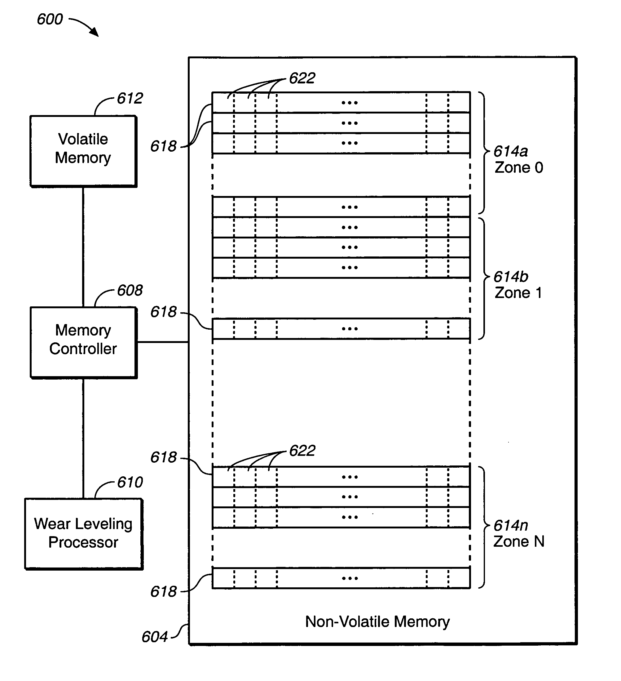
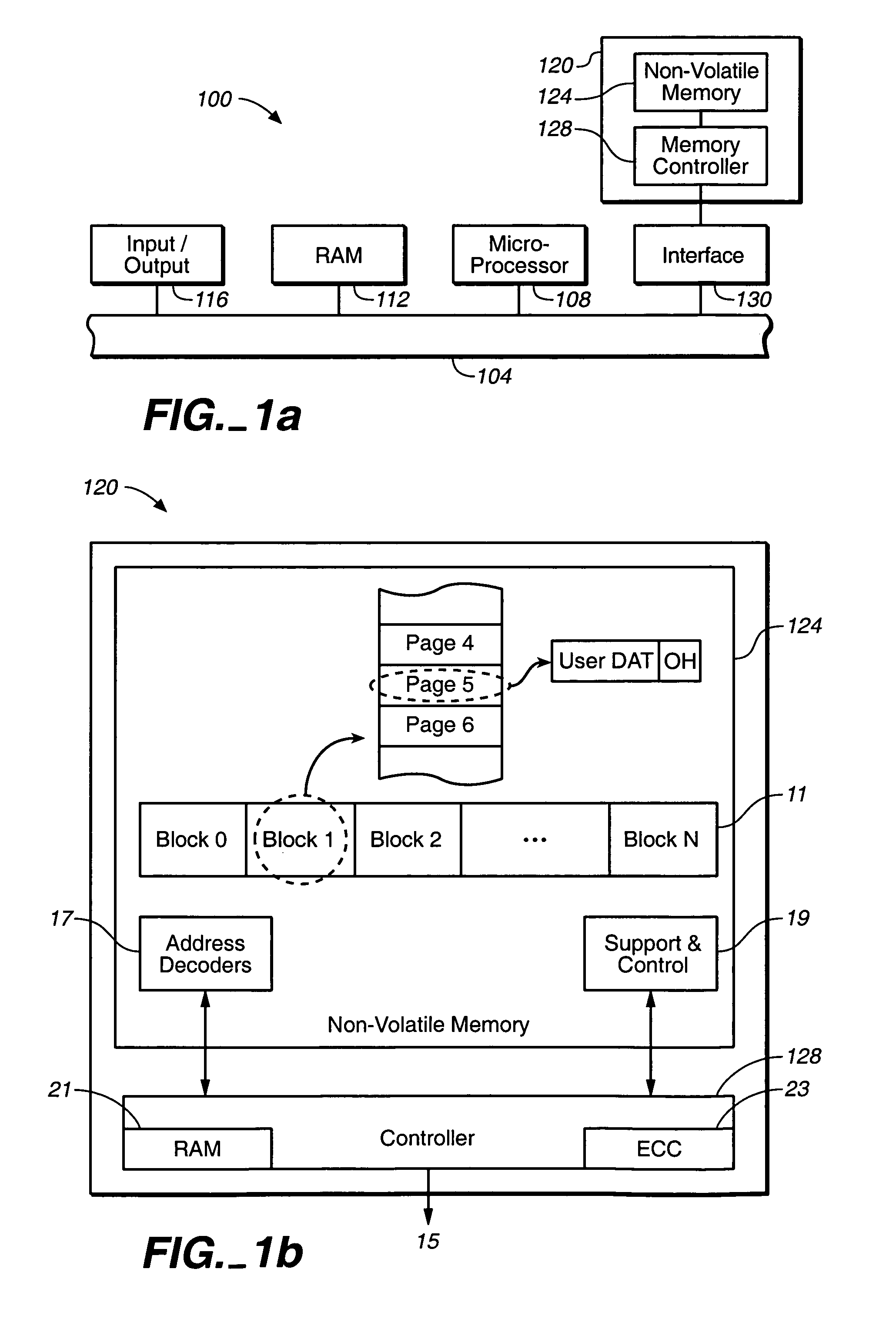
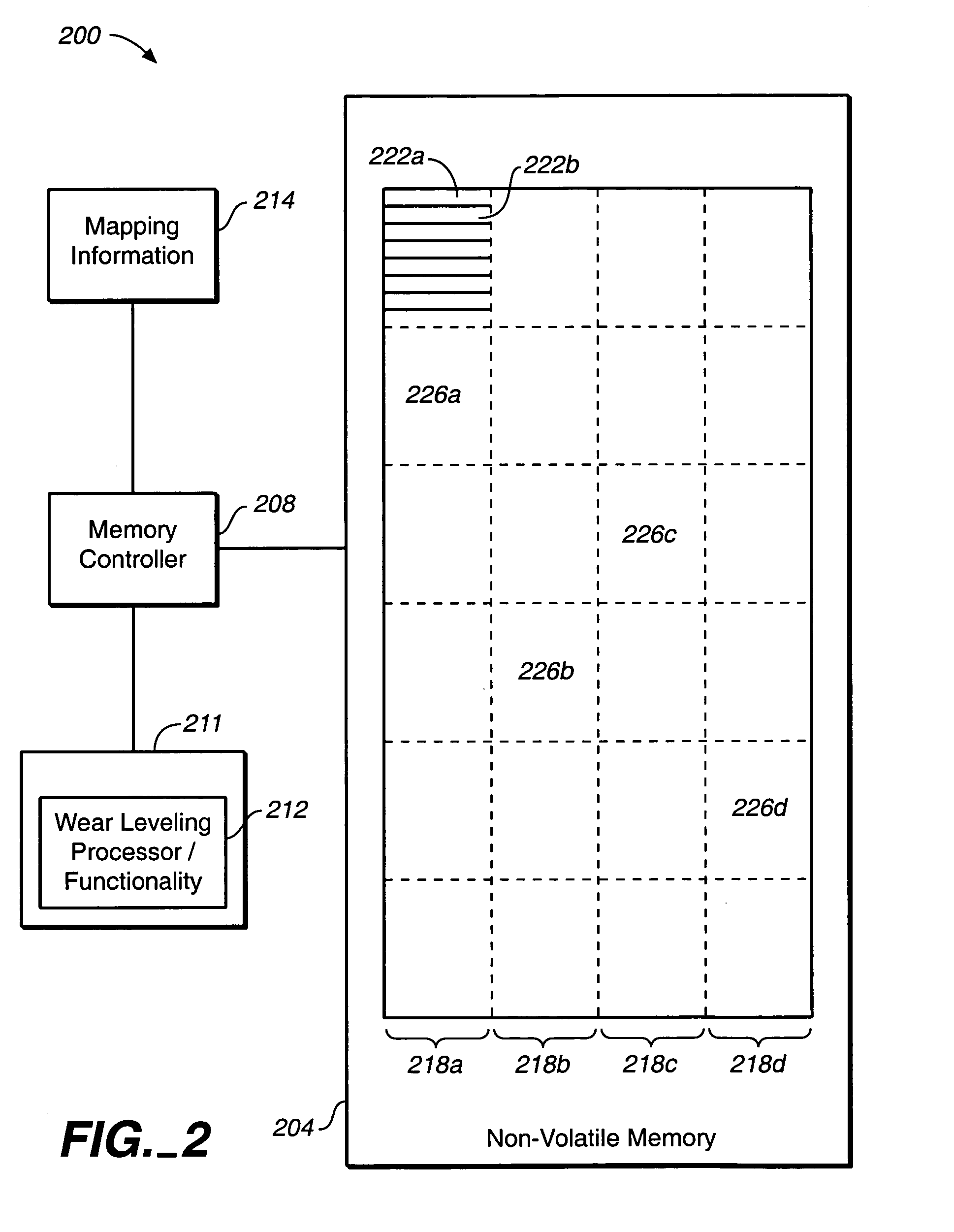
[0038]The present inventions are related to wear leveling in memory systems that are capable of deteriorating in performance over time as the number of erase and write cycles increases. While the embodiments described herein describe non-volatile EEPROM based memory systems, the various aspects of the present inventions are applicable to any type of storage medium susceptible to “wear”. For example, an emerging type of non-volatile memory technology is phase-change memory. Information is stored by changing the phase of a given material. Such systems also may be prone to “wear”, where the storage medium is less capable of storing information as the number of times the medium has been cycled increases. The present inventions can be readily applied to such technologies.

[0039]In one embodiment, non-volatile memory storage cells within flash memory storage systems may be repetitively programmed and erased, although each cell may only be erased ...


PUM


Abstract

Methods and apparatus for performing wear leveling in a non-volatile memory system are disclosed. Included is a method for performing wear leveling in a memory system that includes a first zone, which has a first memory element that includes contents, and a second zone includes identifying the first memory element and associating the contents of the first memory element with the second zone while disassociating the contents of the first memory element from the first zone. In one embodiment, associating the contents of the first memory element with the second involves moving contents of a second memory element into a third memory element, then copying the contents of the first memory element into the second memory element.

Description

CROSS-REFERENCE TO RELATED APPLICATIONS AND PATENTS[0001]The benefit of U.S. provisional Patent Application No. 60 / 422,173, filed Oct. 28, 2002, is claimed herein.[0002]Also related are co-pending U.S. patent application Ser. No. 10 / 281,739 entitled “Wear-Leveling in Non-Volatile Storage Systems,” filed Oct. 28, 2002; co-pending U.S. patent application Ser. No. 10 / 281,823 entitled “Maintaining an Average Erase Count in a Non-Volatile Storage System,” filed Oct. 28, 2002; co-pending U.S. patent application Ser. No. 10 / 281,670 entitled “Tracking the Most Frequently Erased Blocks in Non-Volatile Memory Systems”, filed Oct. 28, 2002; co-pending U.S. patent application Ser. No. 10 / 281,824 entitled “Tracking the Least Frequently Erased Blocks in Non-Volatile Memory Systems”, filed Oct. 28, 2002; co-pending U.S. patent application Ser. No. 09 / 766,436 entitled “Partial Block Data Programming and Reading Operations in a Non-Volatile Memory”, publication no. 2002 / 0099904; and U.S. Pat. Nos. 5...

Claims


Application Information

Patent Timeline
Patent Type & Authority Patents(United States)
IPC IPC(8): G06F12/00G06F13/00G06F12/02G11C16/34G11C29/00
CPCG06F12/0246G11C16/3495G11C29/76G06F2212/1036G06F2212/7211G11C16/349G11C16/08
Inventor GONZALEZ, CARLOS J.CONLEY, KEVIN M.
Owner SANDISK TECH LLC
Why Eureka
Try Eureka