Method of manufacturing rotor of electric motor

a technology of electric motors and rotors, applied in the direction of magnetic circuit rotating parts, magnetic circuit shapes/forms/construction, magnetic bodies, etc., to achieve the effect of low cost, excellent adaptability, and easy to cope with even resonan

Inactive Publication Date: 2006-10-17
FUJITSU GENERAL LTD
View PDF9 Cites 23 Cited by
  • Summary
  • Abstract
  • Description
  • Claims
  • Application Information

AI Technical Summary

Benefits of technology

[0012]According to the present invention, it is possible to manufacture the electric motor at a low cost by realizing vibration isolation, eccentricity and the like of the rotor with a small number of parts. It is also possib

Problems solved by technology

However, there was the followi

Method used


Image

  • Method of manufacturing rotor of electric motor
  • Method of manufacturing rotor of electric motor
  • Method of manufacturing rotor of electric motor

Examples


Embodiment Construction

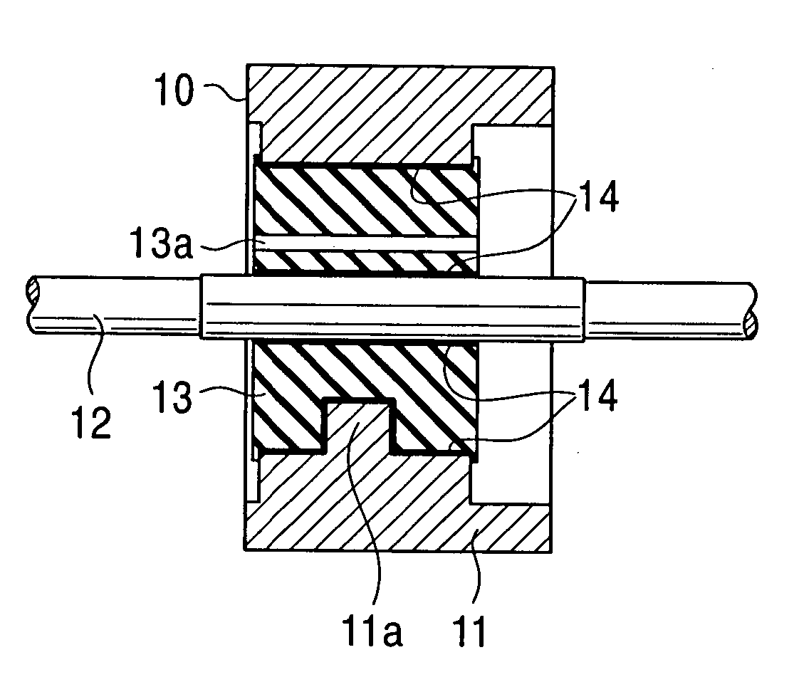
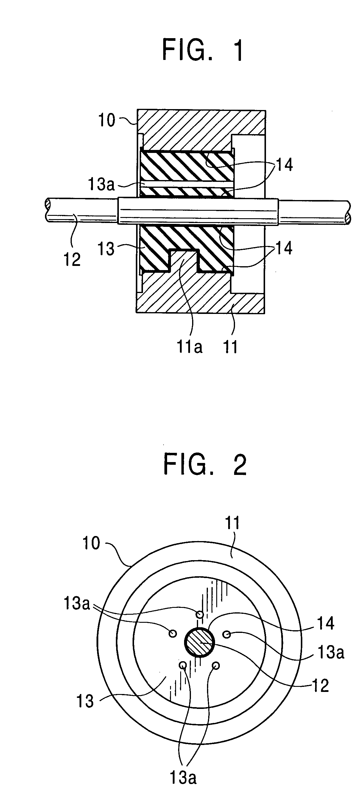
[0028]First, with reference to the cross-sectional view of FIG. 1 and the side view of FIG. 2, the description will be made of an embodiment according to the present invention. In this respect, in the present embodiment, the structure of the stator side for generating a revolving magnetic field has nothing direct to do with the gist of the present invention, and therefore, its illustration is omitted.

[0029]This rotor 10 is provided with a permanent magnet 11 formed in a ring shape; a rotating shaft 12 inserted in the center thereof; and a cushioning member 13 made of rubber material having predetermined hardness, vulcanized and molded between the permanent magnet 11 and the rotating shaft 12. The permanent magnet 11 and the rotating shaft 12 are integrally coupled through the cushioning member 13.

[0030]According to the present embodiment, the permanent magnet 11 is made of plastic magnet, and on the inner peripheral surface thereof, there is formed a protruded portion 11a which ente...


PUM

PropertyMeasurementUnit
Temperatureaaaaaaaaaa
Hardnessaaaaaaaaaa

Abstract

In a method of manufacturing a rotor of an electric motor to be arranged inside a stator, a permanent magnet is formed in a ring-shape, and a rotating shaft and the permanent magnet are concentrically arranged in a mold. Then, a rubber material in a fluid state is poured into a space between the permanent magnet and the rotating shaft to vulcanize and mold a cushioning member having predetermined hardness. The permanent magnet and the rotating shaft are integrally coupled through the cushioning member.

Description

CROSS-REFERENCE TO RELATED APPLICATION[0001]This is a divisional application of Ser. No. 09 / 845,185 filed on May 1, 2001, now abandoned May 1, 2001, which claims priority to Japanese Patent Application No. 2000-145560, filed on May 17, 2001.BACKGROUND OF THE INVENTION[0002]The present invention relates to a method of manufacturing an electric motor for use with a household electrical appliance such as an air conditioner, industrial equipment and the like, and more particularly to a rotor of the electric motor causing little vibration during rotation.[0003]The electric motor has been used for various electrical products, and as regards the air conditioner, in most cases, for its fan motor, there has been used an inner rotor type fan motor, in which a rotor is arranged inside a stator for generating a revolving magnetic field.[0004]As the air conditioner is installed indoors, silence is required of the electric motor. In order to comply with this request, the inner rotor type has been...

Claims


Application Information

Patent Timeline
IPC IPC(8): H02K15/00H02K15/14H02K15/16H02K1/27H02K1/28H02K3/30H02K5/24H02K15/03
CPCH02K1/30H02K3/30H02K15/03Y10T29/49917Y10T29/53143Y10T29/49012Y10T29/49009Y10T29/49076Y10T29/49078
Inventor KOJIMA, TOMONORITANNO, TOSHIAKIMAEYAMA, KENOKUTSU, HIROSHI
Owner FUJITSU GENERAL LTD
Why Eureka
Try Eureka