Method for operating a fuel supply system for an internal combustion engine in a motor vehicle

a technology of fuel supply system and internal combustion engine, which is applied in the direction of machines/engines, electric control, instruments, etc., can solve the problems of sensor failure, high probability, and assumption of fault of pressure sensor, and achieve reliable diagnosis and cost-effective

Inactive Publication Date: 2006-10-17
ROBERT BOSCH GMBH
View PDF20 Cites 25 Cited by
  • Summary
  • Abstract
  • Description
  • Claims
  • Application Information

AI Technical Summary

Benefits of technology

[0003]In contrast, the present invention provides a method for operating a fuel-supply system for an internal combustion engine of a motor vehicle having a fuel-storage tank, a fuel pump, a pressure sensor and a pressure region to which the fuel pump supplies fuel. The pressure sensor is arranged in the pressure region and generates a signal representing the pressure in this region. The signal representing the pressure in the pressure region is evaluated for a diagnosis of the pressure sensor. In contrast to the related art, the method according to the present invention utilizes a pressure sensor in the low-pressure region of a fuel-supply system and may include an additional pressure sensor in the high-pressure region. The diagnosis of the pressure sensor according to the present invention, based on the signal representing the pressure in the pressure region, provides a cost-effective and reliable diagnosis possibility since no increased hardware is required and the diagnosis may be implemented in an engine-control device, which is already present anyway. Furthermore, the signal evaluation within the engine-control device also constitutes a particularly reliable option.

Problems solved by technology

If one of these two conditions is not satisfied, a defect or a fault of the pressure sensor is assumed.
If this irregularity is absent and a constant signal measured instead, it is highly probable that the sensor is defective.

Method used


Image

  • Method for operating a fuel supply system for an internal combustion engine in a motor vehicle
  • Method for operating a fuel supply system for an internal combustion engine in a motor vehicle
  • Method for operating a fuel supply system for an internal combustion engine in a motor vehicle

Examples


Embodiment Construction

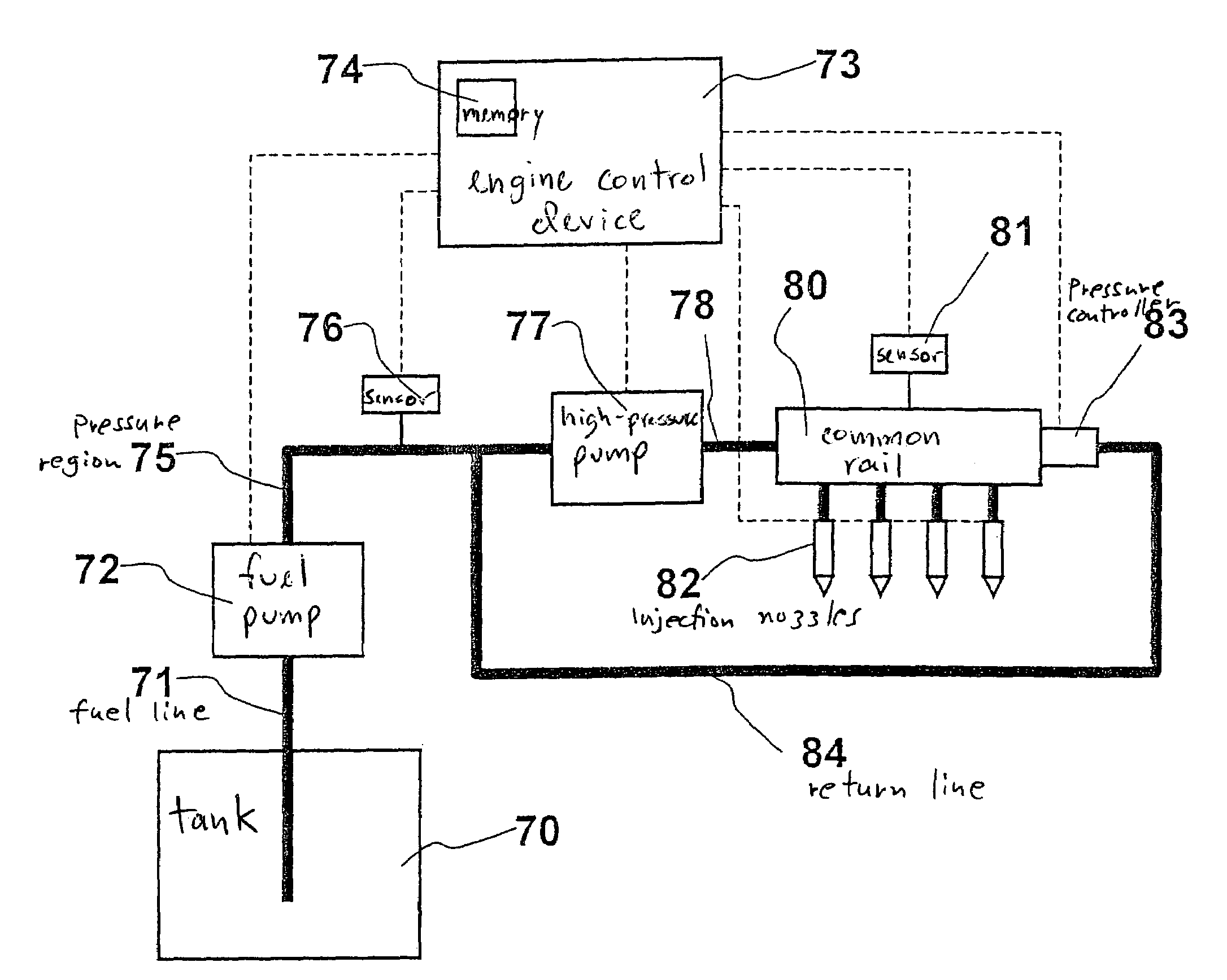
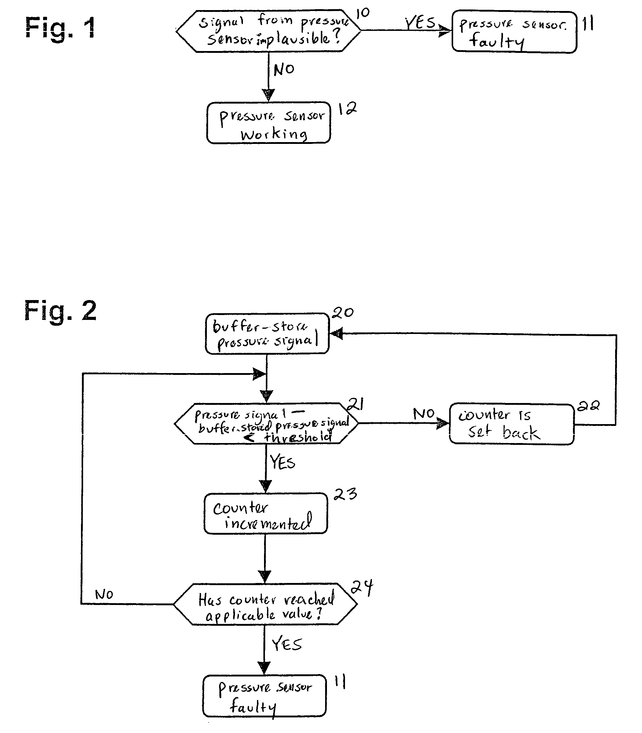
[0021]FIG. 1 shows a first diagnosis option of the method of the present invention. According to the present invention, a pressure sensor 76 is arranged inside a fuel-supply system for an internal combustion engine of a motor vehicle. According to FIG. 7, the sensor 76 is arranged between the electric fuel pump 72, which supplies the fuel from the fuel storage tank, i.e., tank 70, and a post-connected high-pressure pump 77, the pressure sensor measuring the pressure in this intermediate pressure region 75. The pressure signal of this pressure region generated by pressure sensor 76 is analyzed for the diagnosis of pressure sensor 76. A first diagnosis option is to check the pressure value or the voltage value supplied by the sensor with respect to a plausible voltage or signal value. According to FIG. 1, it is checked in a step 10 whether the signal value, or the voltage value, is below a minimum or above a maximum threshold value. If it is determined in step 10 that the signal value...


PUM


Abstract

A method for operating a fuel-supply system for an internal combustion engine of a motor vehicle is provided, the fuel-supply system having a fuel-storage tank, a fuel pump and a pressure sensor, the fuel pump supplying fuel from the fuel-storage tank to a pressure region, the pressure sensor being arranged in the pressure region, and the pressure sensor generating a signal representing the pressure in the pressure region.

Description

FIELD OF THE INVENTION[0001]The present invention relates to a method for operating a fuel-supply system for an internal combustion engine of a motor vehicle having a fuel-storage tank, a fuel pump and a pressure sensor, in which the fuel pump supplies fuel from the fuel-storage tank to a pressure region, and the pressure sensor is arranged in the pressure region in order to generate a signal that represents the pressure in the pressure region.BACKGROUND INFORMATION [0002]German Published Patent Application No. 199 08 352 discloses a fuel-injection method for an internal combustion engine in which the fuel is supplied from the fuel tank into a storage chamber with the aid of an electric fuel pump and a post-connected high-pressure pump. The pressure generated in the storage chamber is measured using a pressure sensor. The system is controlled and regulated to a setpoint value of the pressure in the storage chamber. According to this reference, a fault in the fuel-supply system is de...

Claims


Application Information

Patent Timeline
Patent Type & Authority Patents(United States)
IPC IPC(8): F02M37/04F02D41/22F02D41/38F02M63/02
CPCF02D41/222F02D41/3809F02D41/3836F02D2041/223F02D2200/0602F02M63/0225
Inventor JOOS, KLAUSWOLBER, JENSFRENZ, THOMASWEISS, RUEDIGERAMLER, MARKUSHINN, KARSTEN
Owner ROBERT BOSCH GMBH
Why Eureka
Try Eureka