Supercharge Your Innovation With Domain-Expert AI Agents!

Pneumatically actuated parking brake

a technology of pneumatic actuator and parking brake, which is applied in the direction of brake cylinder, anti-theft devices, braking systems, etc., can solve the problems of increasing cost and reducing the available packaging space for other wheel components, and achieves the effect of simple and effectiv

Inactive Publication Date: 2006-10-17
ARVINMERITOR TECH
View PDF9 Cites 3 Cited by
  • Summary
  • Abstract
  • Description
  • Claims
  • Application Information

AI Technical Summary

Benefits of technology

The system provides a cost-effective and space-efficient solution for vehicles with or without electronic braking systems, ensuring the brake remains locked even if air pressure leaks, and allows for proportional braking and easy release, reducing fatigue on brake components.

Problems solved by technology

This increases cost and reduces available packaging space for other wheel components.
Further, some vehicles have an EBS but do not want the parking brake system to be electronically controlled.

Method used


Image

  • Pneumatically actuated parking brake
  • Pneumatically actuated parking brake
  • Pneumatically actuated parking brake

Examples


Embodiment Construction

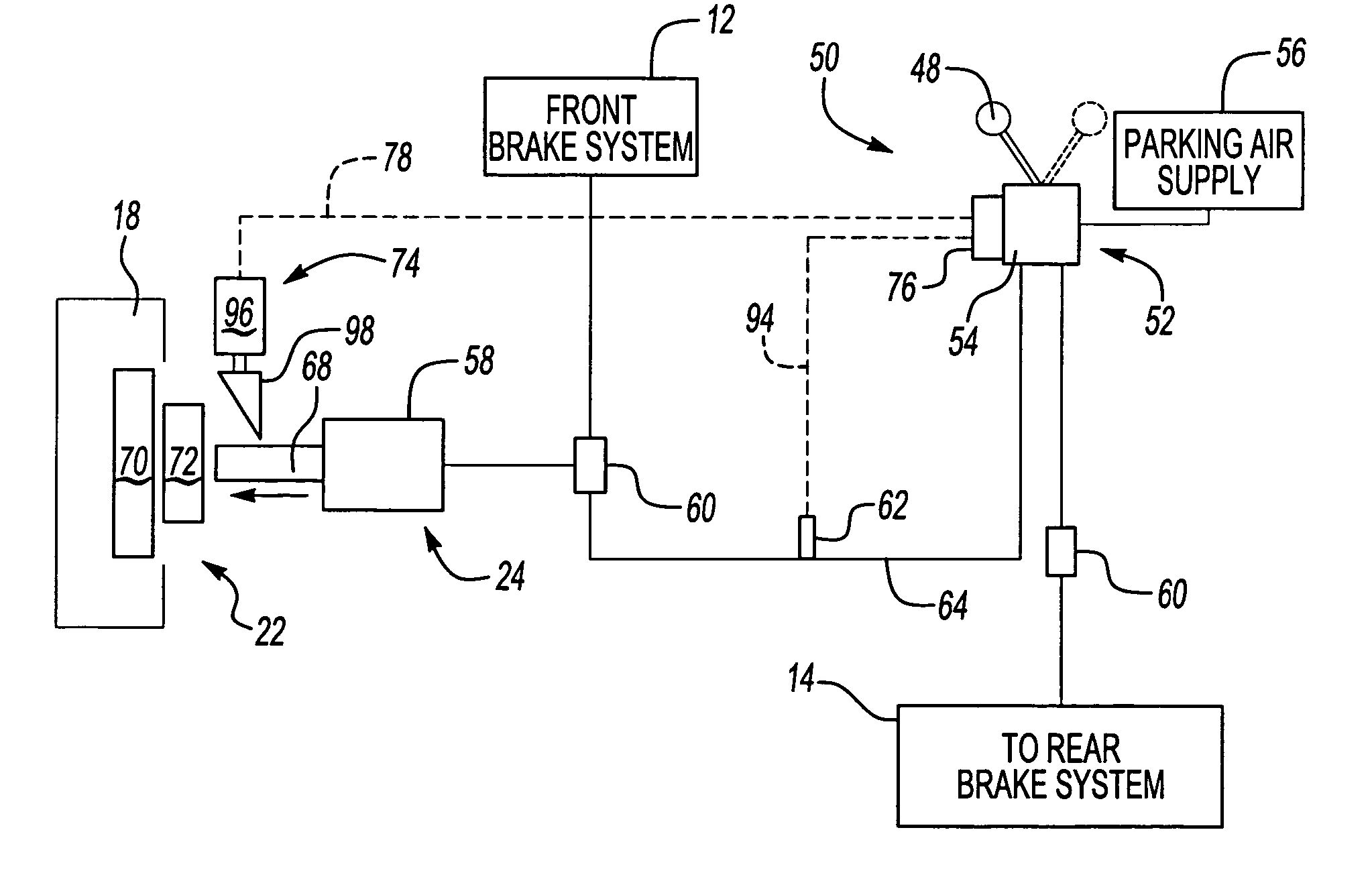
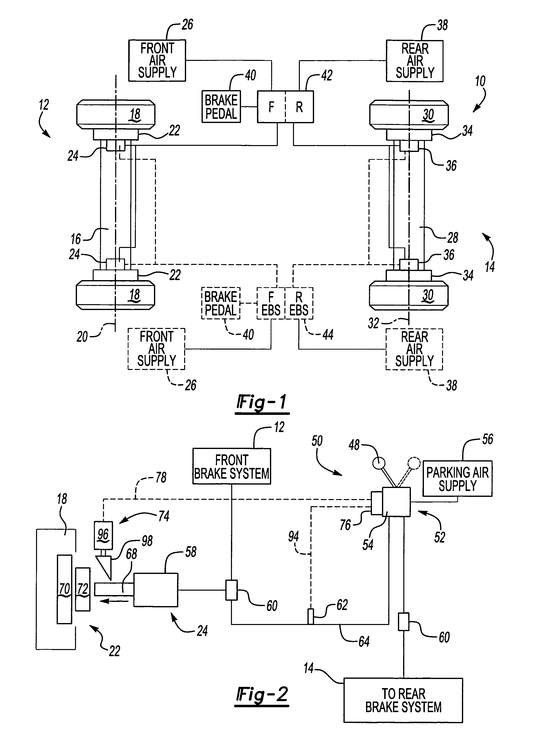
[0022]A vehicle braking system is shown generally at 10 in FIG. 1. The vehicle braking system 10 includes a front brake system 12 and a rear brake system 14. The front brake system 12 brakes a front axle assembly 16 having a pair of front wheels 18 spaced laterally apart from each other along a first lateral axis 20. Each front wheel 18 includes a front brake assembly 22 with a front actuator 24. The front actuators 24 are pneumatically connected to a front air supply 26.

[0023]The rear brake system 14 brakes a rear axle assembly 28 having a pair of rear wheels 30 spaced laterally apart from each other along a second lateral axis 32. Each rear wheel 30 includes a rear brake assembly 34 with a rear actuator 36. The rear actuators 36 are pneumatically connected to a rear air supply 38.

[0024]The rear air supply 38 is preferably separate from the front air supply 26, however, a common air supply for the front 12 and rear 14 brake systems could also be used. It should be understood that t...


PUM


Abstract

A parking brake system uses a pneumatically controlled brake actuator to provide both service and parking brake functions. The parking brake system for a vehicle includes a hand control that is manually movable between a plurality of operational positions. A valve is responsive to movement of the hand control and controls air flow from a parking brake air supply to the pneumatically controlled brake actuator. The valve includes a gate that defines the plurality of operational positions, which include a park position, a release position, and an off position. When the hand control is moved out of the off position and into the park position, the pneumatically controlled brake actuator remains pressurized and a latching mechanism is activated to mechanically lock the vehicle brake. When the hand control is moved to the release position, the vehicle brakes are re-applied to unload the latching mechanism. The parking brake system can be used on vehicles equipped with an electronic braking system, or can be used on vehicles that do not have an electronic braking system.

Description

BACKGROUND OF THE INVENTION[0001]The subject invention relates to a parking brake system for a vehicle including a pneumatically controlled brake actuator that mechanically locks a service brake in a parked condition. The parking brake system can be used in a vehicle having an electronic braking system or can be used in a vehicle that does not have an electronic braking system.[0002]Traditionally, heavy commercial vehicles utilize spring actuators to provide the energy needed for a parking brake function. These heavy commercial vehicles often include electronic braking systems that provide the primary braking function. The primary brake function is a main or foundation brake function that is used to stop or slow rotation of a vehicle wheel during vehicle operation. The parking brake function is usually a separate system that is used to lock a vehicle wheel in a brakes applied position when the vehicle is parked. Traditionally, spring actuators are used for providing the parking and ...

Claims


Application Information

Patent Timeline
Patent Type & Authority Patents(United States)
IPC IPC(8): B60R25/08B60T13/66B60T17/16F16D65/14
CPCB60T13/66B60T17/16F16D65/18F16D2121/02F16D2125/32F16D2127/06
Inventor MCCANN, DENIS JOHN
Owner ARVINMERITOR TECH
Features
  • R&D
  • Intellectual Property
  • Life Sciences
  • Materials
  • Tech Scout
  • Unparalleled Data Quality
  • Higher Quality Content
  • 60% Fewer Hallucinations
Learn More