Treatment device

a treatment device and wound technology, applied in the field of wound treatment devices, can solve the problems of inability of the wound covering to accommodate patient movement, the wound heating process is not controlled by the bandage, and the wound heating cannot be cooled by the patient, so as to improve the comfort and utility of the wound treatment device, the effect of small area and easy deformation

Inactive Publication Date: 2006-10-17
3M INNOVATIVE PROPERTIES CO +1
View PDF101 Cites 67 Cited by
  • Summary
  • Abstract
  • Description
  • Claims
  • Application Information

AI Technical Summary

Benefits of technology

[0010]The transition portion 16 connects the attachment portion 12 to the wound treatment portion 14. This transition portion 16 improves the comfort and utility of the wound treatment device when the patient moves and stretches the wound treatment device 10. This stretching causes the total projected area of the wound treatment device 10 to increase and the shape of the wound treatment device 10 to change. In practice, the bulk of the patient motion is accommodated by the compliance of the transition portion 16. As a consequence, the transition portion projected area 17 increases. The standoff of wound treatment portion 14 rests gently on the patient's skin and it may twist to accommodate patient motion. However since the standoff can slide along

Problems solved by technology

The gauze can adhere to the wound area interfering with the healing process which is undesirable as well.
This traditional form of bandage does not control the thermal environment of the wound and this is undesirable as well.
This result

Method used


Image

  • Treatment device
  • Treatment device
  • Treatment device

Examples


first embodiment

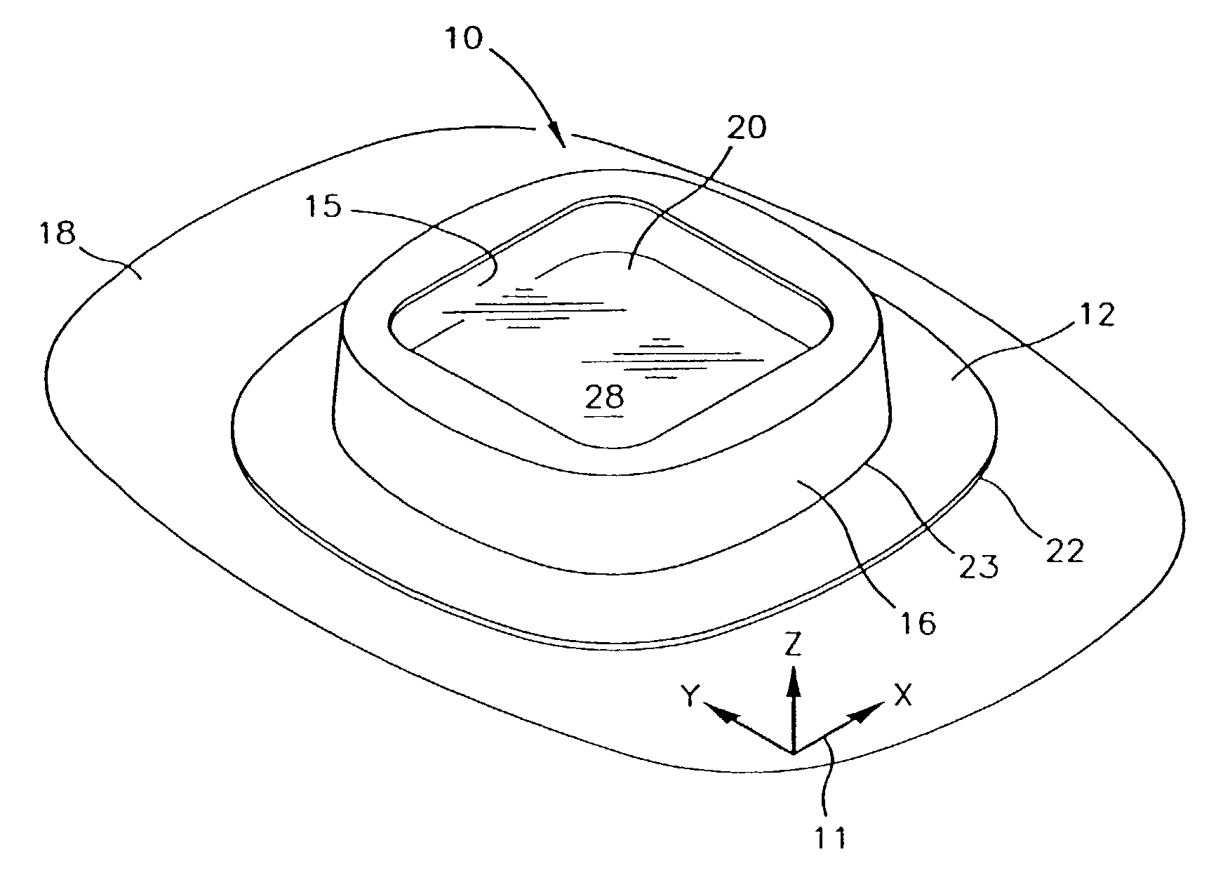
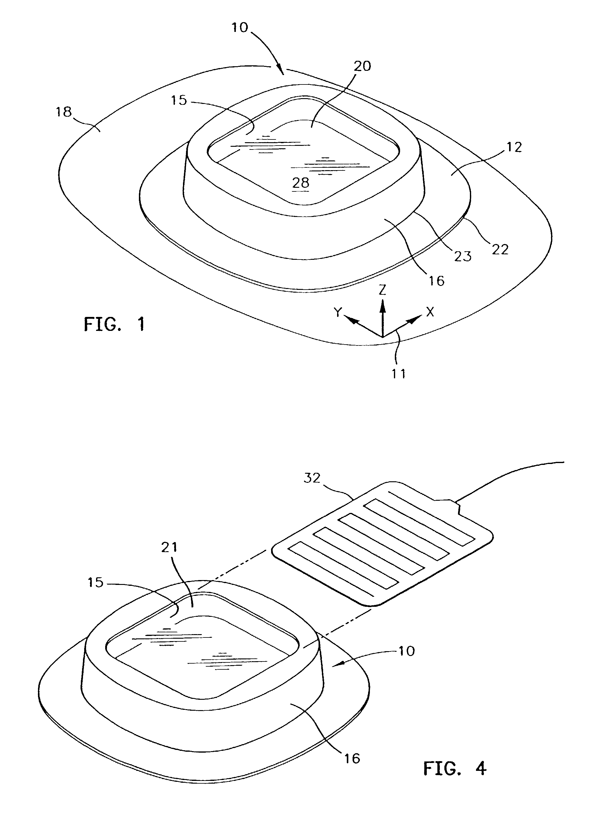
[0033]FIG. 1 is a perspective view of the wound treatment device 10 applied to a patient's skin surface 18. A coordinate system 11 is depicted on the patient's skin surface 18 and it defines X, Y and Z directions. The attachment portion 12 is formed as an planar rim or flange. This element is attached to the patient's skin with an adhesive and it lies in a first XY plane. In this first embodiment of the wound treatment device 10 the transition portion 16 is integrally formed with the attachment portion 12. The transition portion 16 rises vertically from the skin surface in the Z direction to connect to the wound treatment portion 14. In this embodiment the wound treatment portion 14 has a transparent wound cover 20 which allows one to see the wound treatment area 28. The wound cover 20 is supported above the first XY plane by a foam ring standoff 15. The wound cover 20 lies in a second XY plane that is vertically displaced along the Z-axis by the foam ring standoff 15 from the first...

second embodiment

[0039]FIG. 6 is an exploded view of the wound treatment device 10. The attachment portion 12 and transition portion membrane 36 are formed as a unitary composite shell 38. In this embodiment the wound treatment volume is formed by a serrated cup standoff 34. This member made be made from a more rigid polymeric material such as polyethylene or the like. The serrations typified by serration 44 permit the serrated cup to flex and accommodate patient motion. This embodiment shows a release liner 42 coupled to the attachment portion 12 of the composite shell 38 with an adhesive 46.In this embodiment the pocket cover 21 is bonded to the composite shell 38.

[0040]FIG. 7 depicts a power supply to permit the ambulatory use of the heated versions of the wound treatment device. A collection of battery cells may be wired together to form the power supply 48 which may be conveniently attached to a belt 49. A suitable cable 50 may be used to conduct power to the heater 32. In many instances it may...


PUM


Abstract

A treatment device having a first portion in a first plane, a treatment portion with a cover in a second plane that defines a treatment volume extending between the first and second planes, and a flexible transition portion that connects the first portion to the treatment portion. The treatment portion including a polymeric foam ring having interior and exterior walls extending from the first plane to the second plane. The cover spanning the interior wall thereby forming a closed treatment volume. The polymeric foam ring may be impregnated with a medicament selected from the group including an antibiotic material, an antifungal material, an antimicrobrial material, a deodorant material and nitric oxide. The cover may include a pocket for use with an accessory, such as a heater or mapping grid.
A method of treating a treatment area on a patient's skin with the treatment device. The treatment device includes a closed treatment volume having polymeric foam ring impregnated with a medicament. The treatment device is attached to the patient's skin, such that the closed treatment volume encloses the treatment area. The medicament is released into the treatment volume to bring the medicament into contact with the treatment area. Additional steps may include inserting a heater into the pocket or inserting the mapping grid into the pocket and tracking the treatment area with the mapping grid.

Description

CROSS REFERENCE TO RELATED APPLICATIONS[0001]This is a continuation of U.S. patent application Ser. No. 09 / 815,530, filed Mar. 23, 2001, now U.S. Pat. No. 6,468,295 which is a continuation of U.S. patent application Ser. No. 09 / 434,411, filed Nov. 4, 1999, now U.S. Pat. No. 6,248,084 B1, which is a continuation application of U.S. patent application Ser. No. 08 / 965,588, filed Nov. 6, 1997, now U.S. Pat. No. 6,010,527, which is a continuation of U.S. patent application Ser. No. 08 / 342,741, filed Nov. 21, 1994, now U.S. Pat. No. 5,817,145.TECHNICAL FIELD[0002]The invention relates to a wound treatment device for covering and in some applications heating skin lesions, surgical wounds and the like. The wound treatment device includes a wound cover which can support a detachable planar wound heater. The wound covering provides a non-contact wound treatment volume over the wound area. The planar heater supplies or reflects heat from the wound area. The invention also relates to and addres...

Claims


Application Information

Patent Timeline
IPC IPC(8): A61F7/00A61F5/00A61F7/12A61F7/08A61F7/02A61F13/00A61F13/02A61F15/00
CPCA61F7/007A61F13/0203A61F15/008A61F2007/0001A61F2007/0071A61F2007/0078A61F2007/0088A61F2007/0226A61F2013/00165A61F2013/00182A61F2013/00195A61F2013/002A61F2013/00212A61F2013/00387A61F2013/00561A61F2013/00565A61F2013/0057A61F2013/0074A61F2013/00817A61F2013/00846A61F2013/0091A61F2013/00914A61F2013/00919
Inventor AUGUSTINE, SCOTT D.ARNOLD, RANDALL C.HAMLIN, GREGORY P.STAPF, DONALD E.
Owner 3M INNOVATIVE PROPERTIES CO
Why Eureka
Try Eureka