Supercharge Your Innovation With Domain-Expert AI Agents!

Method of fabricating film carrier

a film carrier and film technology, applied in the direction of printed element electric connection formation, dielectric characteristics, semiconductor/solid-state device details, etc., can solve the problems of increasing the increasing the production cost of the film carrier, and affecting the production efficiency of the material, so as to shorten the production time and reduce the production cost

Inactive Publication Date: 2006-10-17
SUBTRON TECH
View PDF5 Cites 0 Cited by
  • Summary
  • Abstract
  • Description
  • Claims
  • Application Information

AI Technical Summary

Benefits of technology

[0010]Accordingly, the present invention is directed to a method of fabricating a film carrier capable of shortening production time and lowering production cost.
[0017]In an embodiment of the present invention, an etching operation is performed to form the holes in the film so that the cost of providing a set of cutting tools for punching holes in the film can be avoided. In addition, the surface of the film is flat and free of holes when the metallic layer is formed over the film. Thus, the metallic layer can adhere uniformly to the film surface and avoid any unevenness around the openings.

Problems solved by technology

In other words, excessive time and labor are needed for fabricating necessary cutting tools, thereby increasing the cost of the film carrier.
Hence, the metallic layer may have some unevenness around the openings.

Method used


Image

  • Method of fabricating film carrier
  • Method of fabricating film carrier
  • Method of fabricating film carrier

Examples


Embodiment Construction

[0022]Reference will now be made in detail to the present preferred embodiments of the invention, examples of which are illustrated in the accompanying drawings. Wherever possible, the same reference numbers are used in the drawings and the description to refer to the same or like parts.

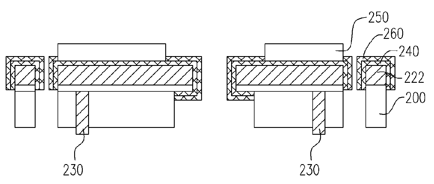
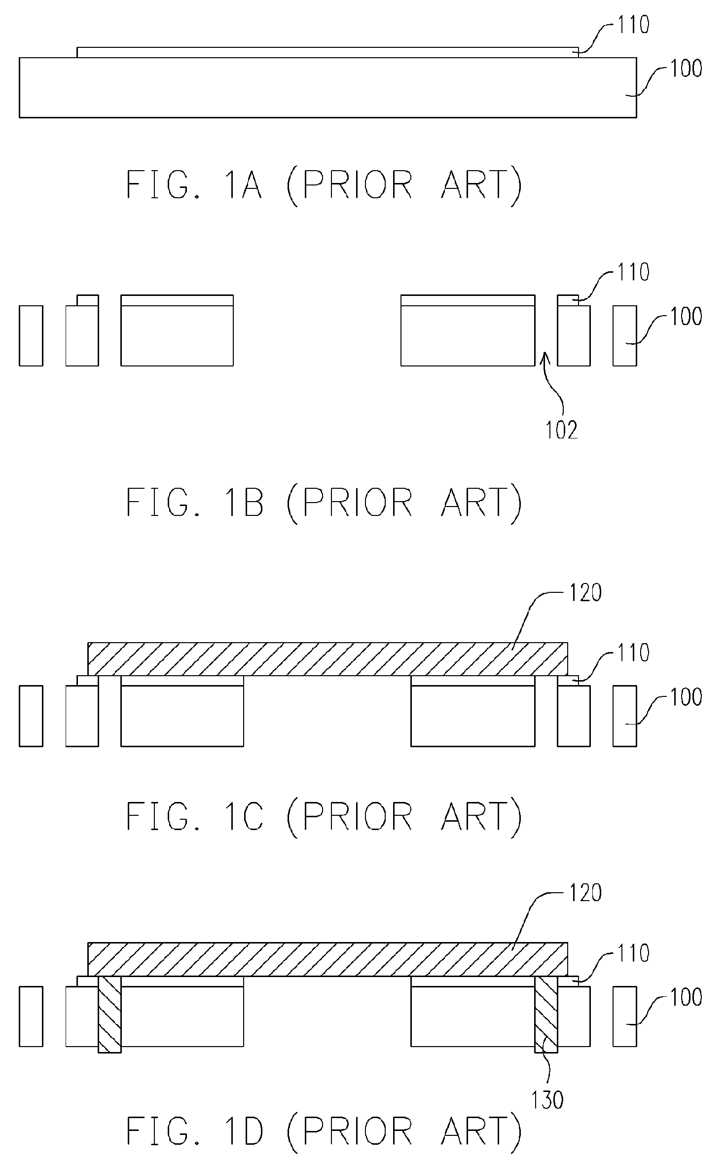
[0023]FIGS. 2A through 2J are schematic cross-sectional views showing the progression of steps of fabricating a film carrier according to one embodiment of the present invention. As shown in FIG. 2A, a film 200 such as a polyimide film having an adhesive layer 210 thereon is provided. The adhesive layer 210 mainly serves to increase the adhesive strength of the film 200 with a subsequently added material layer. Thereafter, as shown in FIG. 2B, a metallic layer 220 is formed over the film 200. In the presence of the adhesive layer 210, the bonding strength between the film 200 and the metallic layer 220 is enhanced. The metallic layer 220 is, for example, a copper layer (or copper foil) or other condu...


PUM

PropertyMeasurementUnit
metallicaaaaaaaaaa
flexibleaaaaaaaaaa
bonding strengthaaaaaaaaaa

Abstract

A method of fabricating a film carrier is provided. The method comprises the steps of providing a film; forming a metallic layer on the film, patterning the metallic layer by etching to form a plurality of metallic leads; and, patterning the film by etching to form a plurality of openings so that processing time and manufacturing cost are reduced.

Description

CROSS-REFERENCE TO RELATED APPLICATION[0001]This application claims the priority benefit of Taiwan application serial no. 93105345, filed on Mar. 2, 2004.BACKGROUND OF THE INVENTION[0002]1. Field of the Invention[0003]The present invention relates to a method of fabricating a carrier. More particularly, the present invention relates to a method of fabricating a film carrier.[0004]2. Description of Related Art[0005]With the great advance in the electronics industry, many types of multifunctional electronic products have become indispensable in our daily life. Most electronic products are driven or controlled by integrated circuits on a die. To protect the structurally weak die and facilitate reliable signal transmission, the die is generally enclosed within a package. In the past, many types of chip packages have been developed. The most common chip bonding techniques include wire bonding (W / B), flip chip (F / C) bonding and tape automatic bonding (TAB). In the TAB technique, a silicon...

Claims


Application Information

Patent Timeline
Patent Type & Authority Patents(United States)
IPC IPC(8): B44C1/22C03C15/00C03C25/68C23F1/00H01B13/00H01L21/48H01L23/28H01L23/498H05K1/00H05K3/00H05K3/06H05K3/24H05K3/38H05K3/40
CPCH01L21/4846H01L23/4985H05K1/028H05K3/4092H01L2924/0002H05K3/002H05K3/064H05K3/244H05K3/383H05K2201/0133H05K2201/0166H05K2201/0394H05K2201/0397H05K2203/0574H01L2924/00
Inventor HU, DYI-CHUNGHUANG, CHIH-KUNGWU, CHIEN-NAN
Owner SUBTRON TECH
Features
  • R&D
  • Intellectual Property
  • Life Sciences
  • Materials
  • Tech Scout
  • Unparalleled Data Quality
  • Higher Quality Content
  • 60% Fewer Hallucinations
Learn More