Adder tree structure digital signal processor system and method

a digital signal processor and adder tree technology, applied in computing, instruments, computation using denominational number representation, etc., can solve the problems of shortfall in dsp performance and the area of semiconductor material necessary for their implementation

US7124162B2Active Publication Date: 2006-10-17NXP USA INC
6 Cites 2 Cited by

Patent Information

Authority / Receiving Office
US · United States
Patent Type
Patents(United States)
Current Assignee / Owner
Publication Date
2006-10-17

Smart Images

  • Figure 1
    Figure 1
  • Figure 2
    Figure 2
  • Figure 3
    Figure 3
Patent Text Reader

Abstract

A Wallace tree structure such as that used in a digital signal processor (DSP) is arranged to sum vectors. The structure has a number of adder stages, each of which may have half adders with two input nodes, and full adders with three input nodes. The structure is designed with reference to the vectors to be summed. The number of full- and half-adders in each stage and the arrangement of vector inputs depends upon their characteristics. An algorithm calculates the possible tree structures and input arrangements, and selects an optimum design having a small final stage ripple adder after the last stage of the Wallace tree structure, the design being based upon the characteristics of the vector inputs. This leads to reduced propagation delay and a reduced amount of semiconductor material for implementation of the DSP.
Need to check novelty before this filing date? Find Prior Art

Description

FIELD OF THE INVENTION

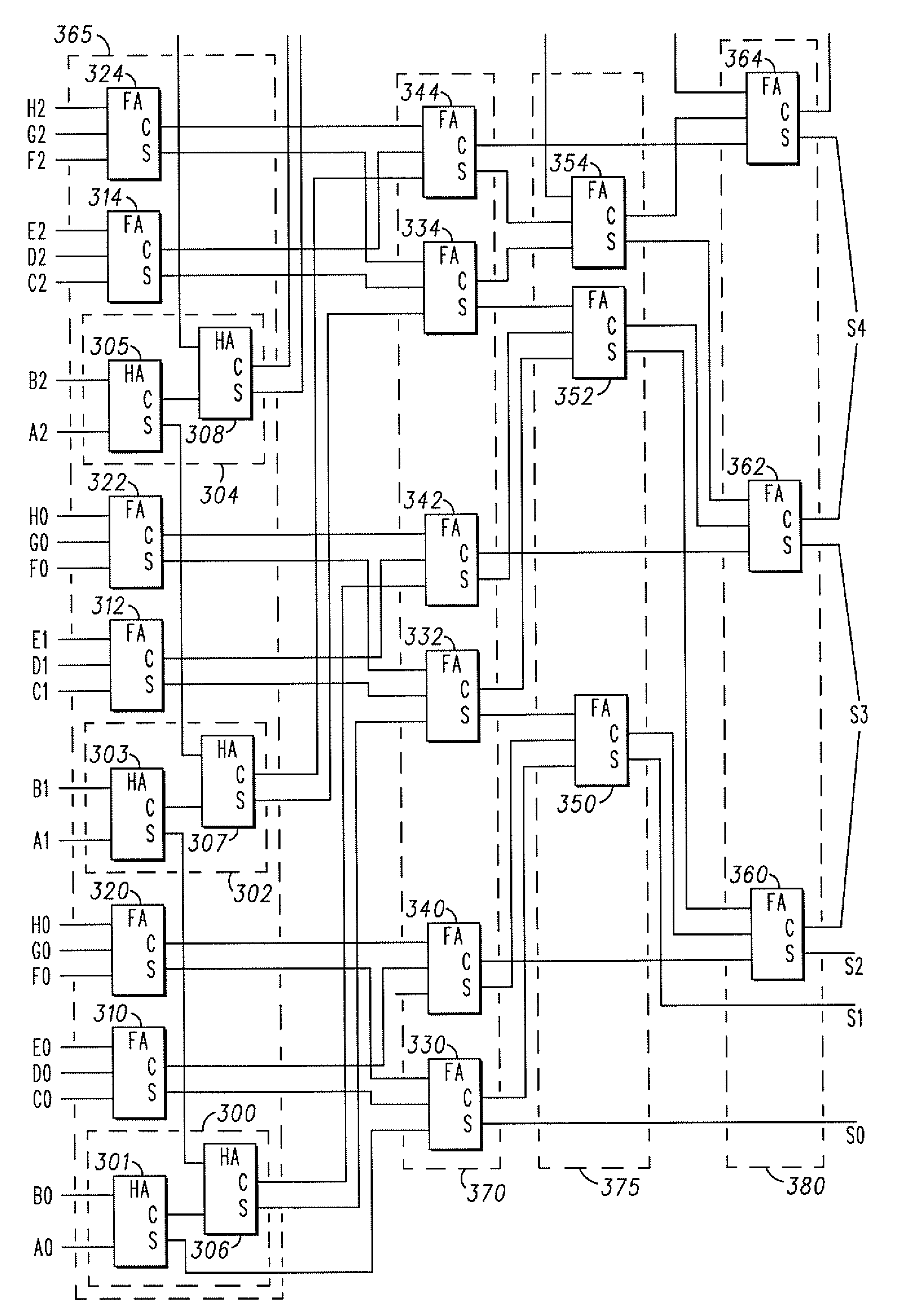
[0001] This invention relates to adder tree structures commonly used in electronic hardware to sum vectors, and particularly but not exclusively to such structures when used in a multiplier to sum partial products produced in a multiplication process.BACKGROUND OF THE INVENTION

[0002] In the field of this invention a Wallace tree is a well known implementation of an adder tree designed to sum vectors with a minimum propagation delay. Rather than completely adding the partial products in pairs as known in a ripple adder tree, a Wallace tree sums up all the bits of the same weights in a merged tree. Typically, full adders are used in Carry-Save-Add (CSA) units, so that 3 equally weighted bits are combined to produce two bits: one bit being the carry, and the other bit being the sum. Each layer of the tree therefore reduces the number of vectors by a factor of 3:2. The tree has as many layers as is necessary to reduce the number of vectors to two of each weight (a ca...

Examples

Embodiment Construction

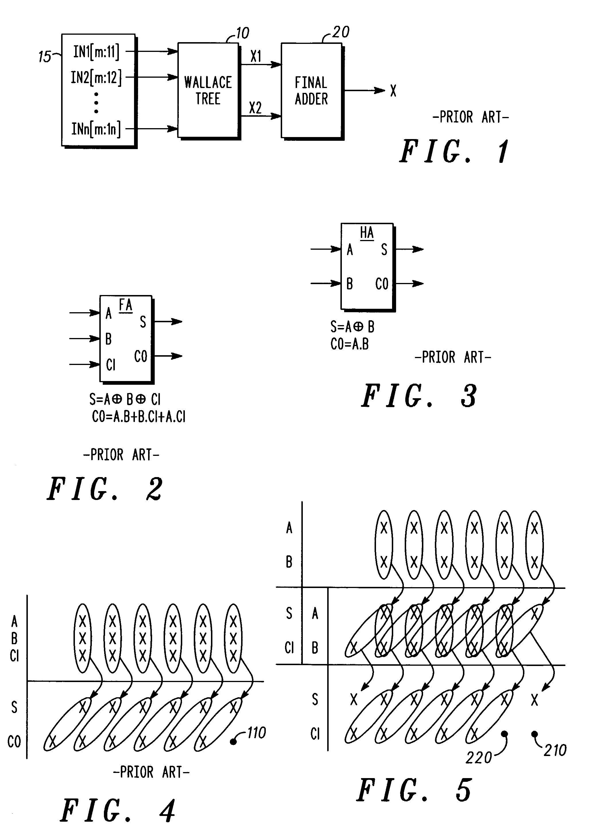
[0024]Referring firstly to FIG. 1, a known vector adder is shown, using a Wallace tree 10 to sum up n number of IN vectors 15 (IN1[m:11] to INn[m:ln]), where m is the number of bits per vector and 1 is the lowest vector index (the least significant bit of the vector) having a non-zero value in each case.

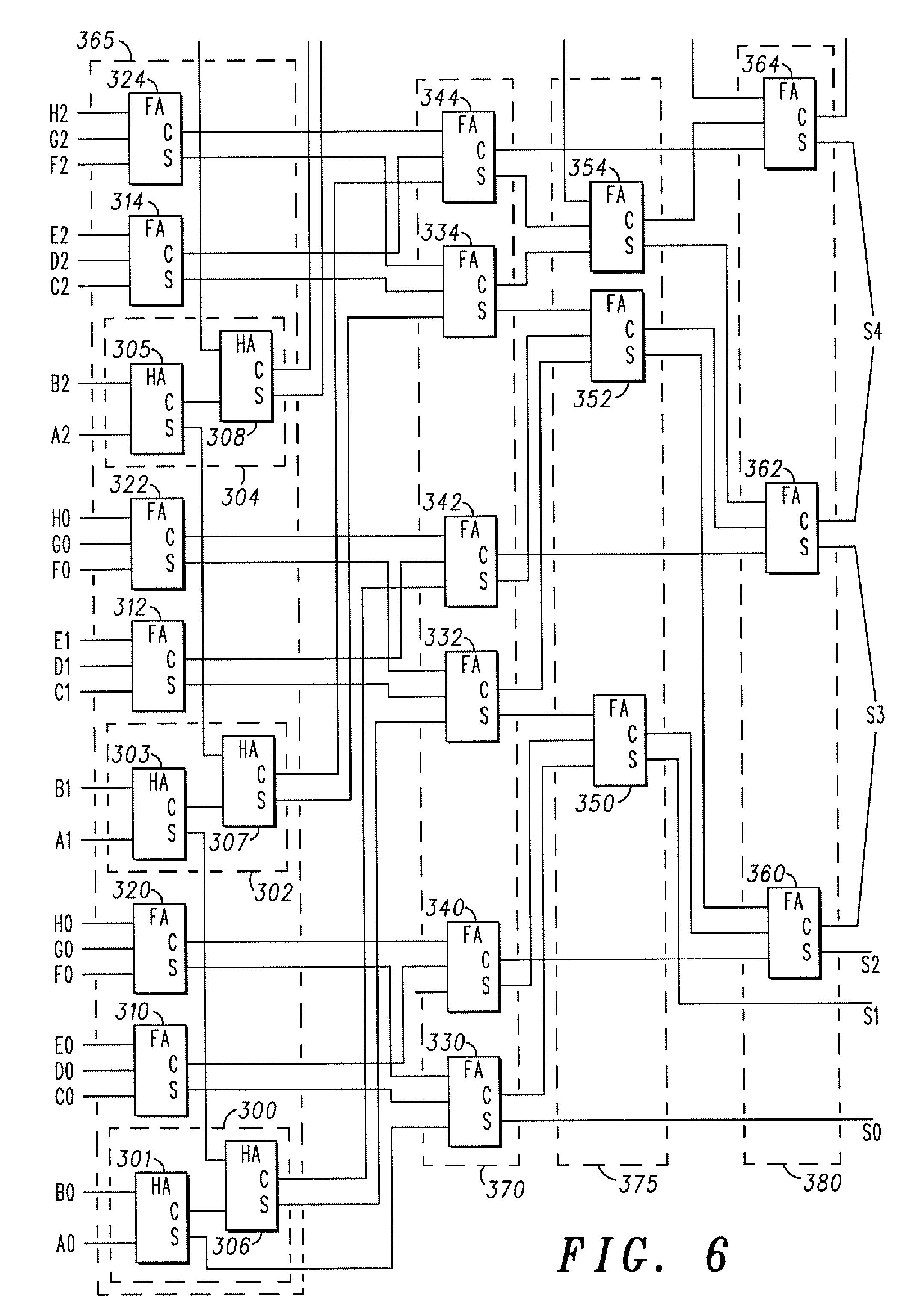
[0025]The Wallace tree 10 comprises a number of stages, each stage composed of Carry-Save Full-or Half-Adders (FA or HA). A FA is shown in FIG. 2, and a HA is shown in FIG. 3. The FA takes three vectors A, B and CI (carry-in), and provides outputs S (Sum) and CO (carry-out). These are calculated as follows:

S=A⊕B⊕CI

CO=A.B+B.CI+A.CI

[0026]The HA takes two vectors A and B, and provides outputs S (Sum) and CO (carry-out). These are calculated as follows:

S=A⊕B

CO=A.B

[0027]The Wallace tree structure reduces the summation process into intermediate stages. In a simple arrangement using only FAs, the ratio of input to output vectors will be 3:2 for each stage, leading to a reduction in the numb...