Dual fuel injection valve and method of operating a dual fuel injection valve

a dual fuel injection and valve technology, applied in the direction of fuel injecting pumps, machines/engines, mechanical equipment, etc., can solve the problems of diesel-fuelled engines that use such an approach, and the fuel is typically required much higher temperatures and pressures to auto-ignite the fuel

Inactive Publication Date: 2006-10-24
WESTPORT FUEL SYST CANADA INC
View PDF13 Cites 56 Cited by
  • Summary
  • Abstract
  • Description
  • Claims
  • Application Information

AI Technical Summary

Benefits of technology

[0056]Yet another embodiment of the method further comprises increasing the pressure of the second fuel in a second fuel cavity to move t...

Problems solved by technology

Engines using such an approach have been unable to match the power, performance, and efficiency of diesel-fuelled engines.
A problem with gase...

Method used


Image

  • Dual fuel injection valve and method of operating a dual fuel injection valve
  • Dual fuel injection valve and method of operating a dual fuel injection valve
  • Dual fuel injection valve and method of operating a dual fuel injection valve

Examples


Embodiment Construction

)

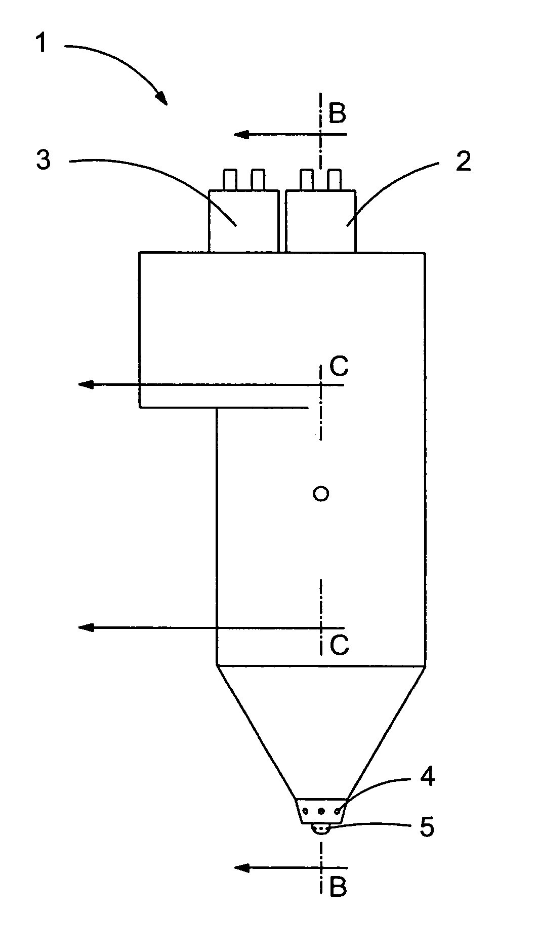
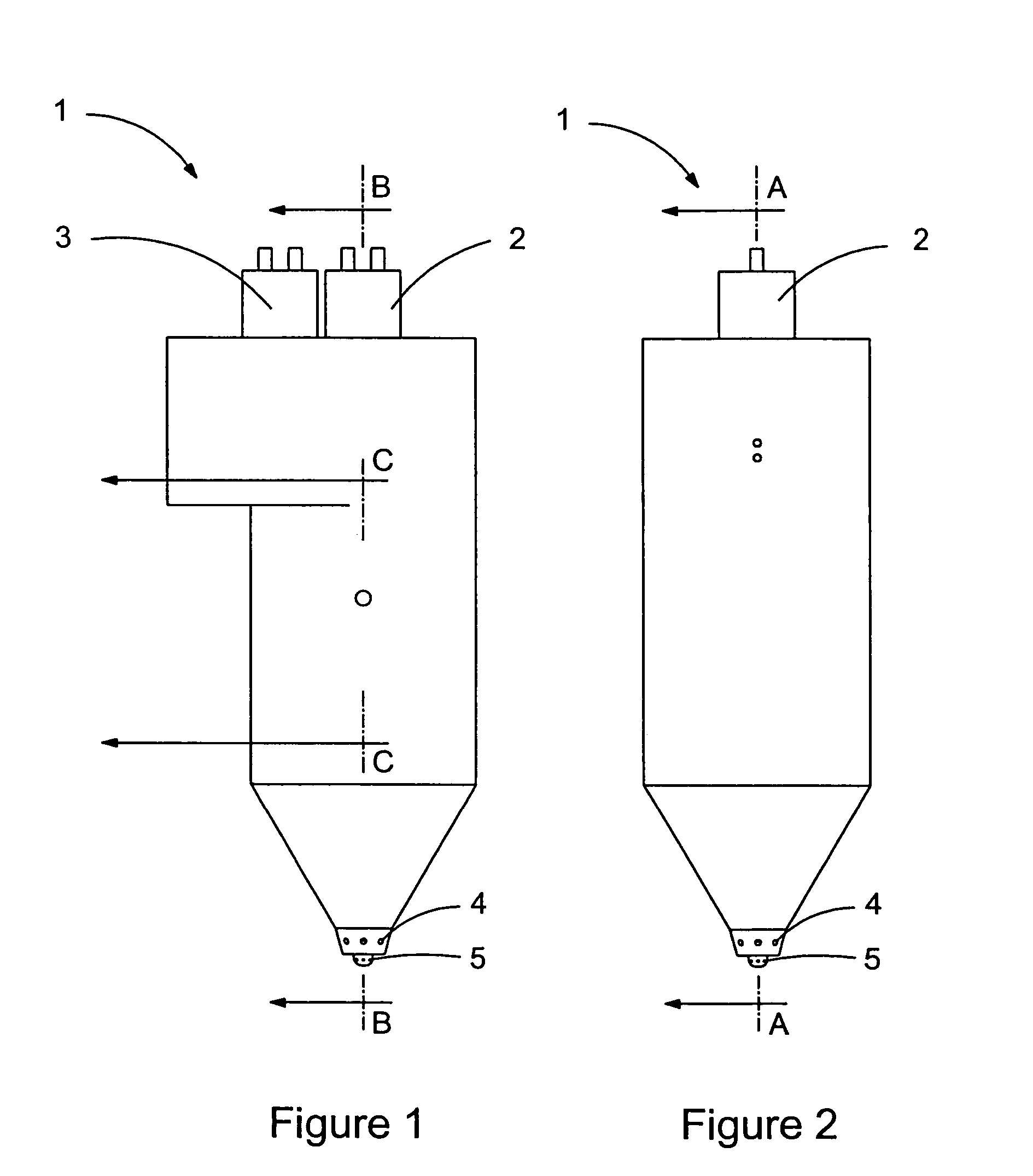
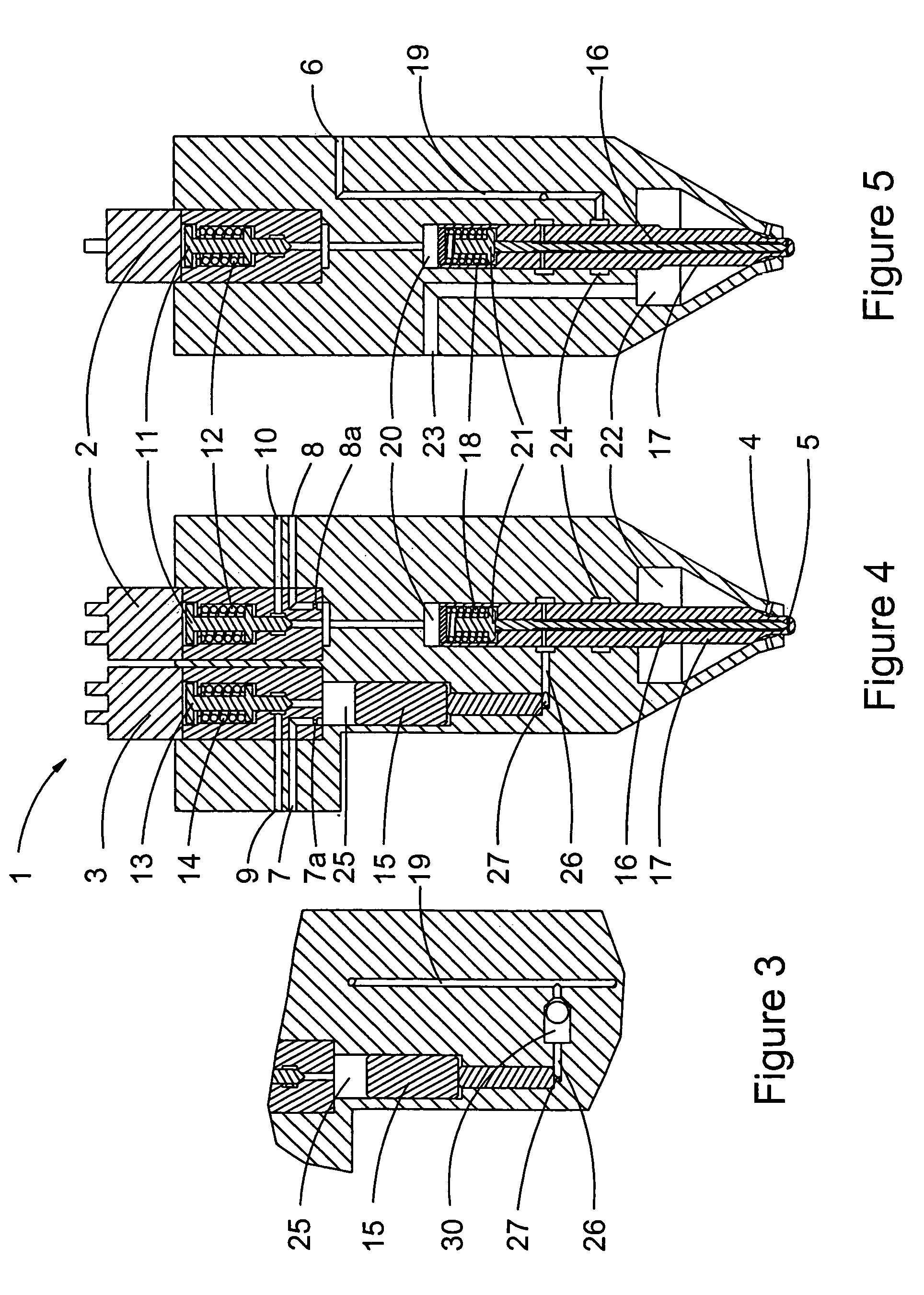
[0065]A dual fuel injection valve is capable of independently and separately injecting a pilot fuel and a main fuel into a combustion chamber of an internal combustion engine. That is, the injection valve provides independent control of the injection timing and the fuel quantity for the pilot fuel and main fuel. In addition, the pilot fuel and main fuel are injected into the combustion chamber separately, through different ejection ports.

[0066]The main fuel is a fuel that is cleaner burning than conventional diesel fuel such that substitution of the main fuel for diesel fuel results in lower emissions of particulate matter and / or nitrogen oxides (NOx) compared to an equivalent conventional engine that burns only diesel fuel. Preferably, on average, the main fuel comprises more than 90% of the fuel consumed by the engine measured on an energy basis.

[0067]In preferred embodiments, the main fuel is a gaseous fuel such as natural gas, propane or hydrogen, and the pilot fuel is a liqu...


PUM


Abstract

A dual fuel injection valve separately and independently injects two different fuels and comprises a dual needle assembly with a hollow open-ended outer needle and an inner needle disposed within the hollow interior. A cap cooperates with the outer needle to cover the open end, and the outer needle and the cap together comprise the inner valve body. The outer and inner needles are each movable independently from each other between respective open and closed positions. A spring disposed between the cap and the inner needle contributes to biasing the inner needle in the closed position. The cap can be joined to the outer needle, whereby the cap can provide a limit to the movement of the inner needle. In another embodiment the cap can be detached from the outer body, allowing the spring to space the cap away from the outer needle, assisting with biasing the outer needle closed.

Description

CROSS-REFERENCE TO RELATED APPLICATION(S) [0001]This application is a divisional of U.S. patent application Ser. No. 09 / 989,623 filed Nov. 20, 2001 now U.S. Pat. No. 6,761,325, which is a continuation-in-part of U.S. patent application Ser. No. 09 / 552,480 filed Apr. 18, 2000 now U.S. Pat. No. 6,336,598, entitled “Gaseous and Liquid Fuel Injection Valve with a Two-Way Hydraulic Fluid Control Valve”, which is a continuation-in-part of U.S. patent application Ser. No. 09 / 154,103 filed Sep. 16, 1998, entitled “Gaseous and Liquid Fuel Injection Valve”, now U.S. Pat. No. 6,073,862 issued Jun. 13, 2000. The '103 and the '480 applications are incorporated herein by reference in their entirety.FIELD OF THE INVENTION [0002]The present invention relates to a hydraulically actuatable dual fuel injection valve and a dual needle assembly, for injecting two different fuels into the combustion chamber of an internal combustion engine.BACKGROUND OF THE INVENTION [0003]Because of its ready availabili...

Claims


Application Information

Patent Timeline
IPC IPC(8): F02D1/06B05B1/30F02M39/00F02M47/02F02M59/00F02M21/02F02M43/02F02M43/04F02M45/08F02M47/04F02M47/06F02M57/02F02M59/10F02M61/16F02M61/18F02M61/20F02M63/00
CPCF02M43/02F02M45/086F02M47/027F02M47/043F02M47/046F02M47/06F02M57/025F02M59/105F02M61/168F02M61/182F02D19/0694F02D19/10F02M21/0263F02M21/0254F02M43/04Y02T10/36F02M61/20F02M63/0064F02M2200/46Y02T10/32Y02T10/30
Inventor BAKER, S. MICHAELMUMFORD, DAVIDPOST, ADRIANLENNOX, TIMDOUVILLE, BRADLEY D.TOUCHETTE, ALAIN M. J.
Owner WESTPORT FUEL SYST CANADA INC
Why Eureka
Try Eureka