Gas generator
a generator and gas technology, applied in the direction of electric fuzes, pedestrian/occupant safety arrangements, lighting and heating apparatus, etc., can solve the problems of expensive cutting, and achieve the effect of reducing production costs, not requiring expensive cutting, and being convenient to us
- Summary
- Abstract
- Description
- Claims
- Application Information
AI Technical Summary
Benefits of technology
Problems solved by technology
Method used
Image
Examples
embodiment 1
(1) Embodiment 1
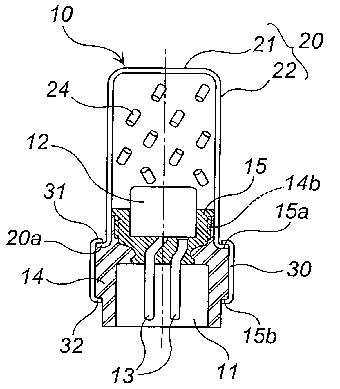
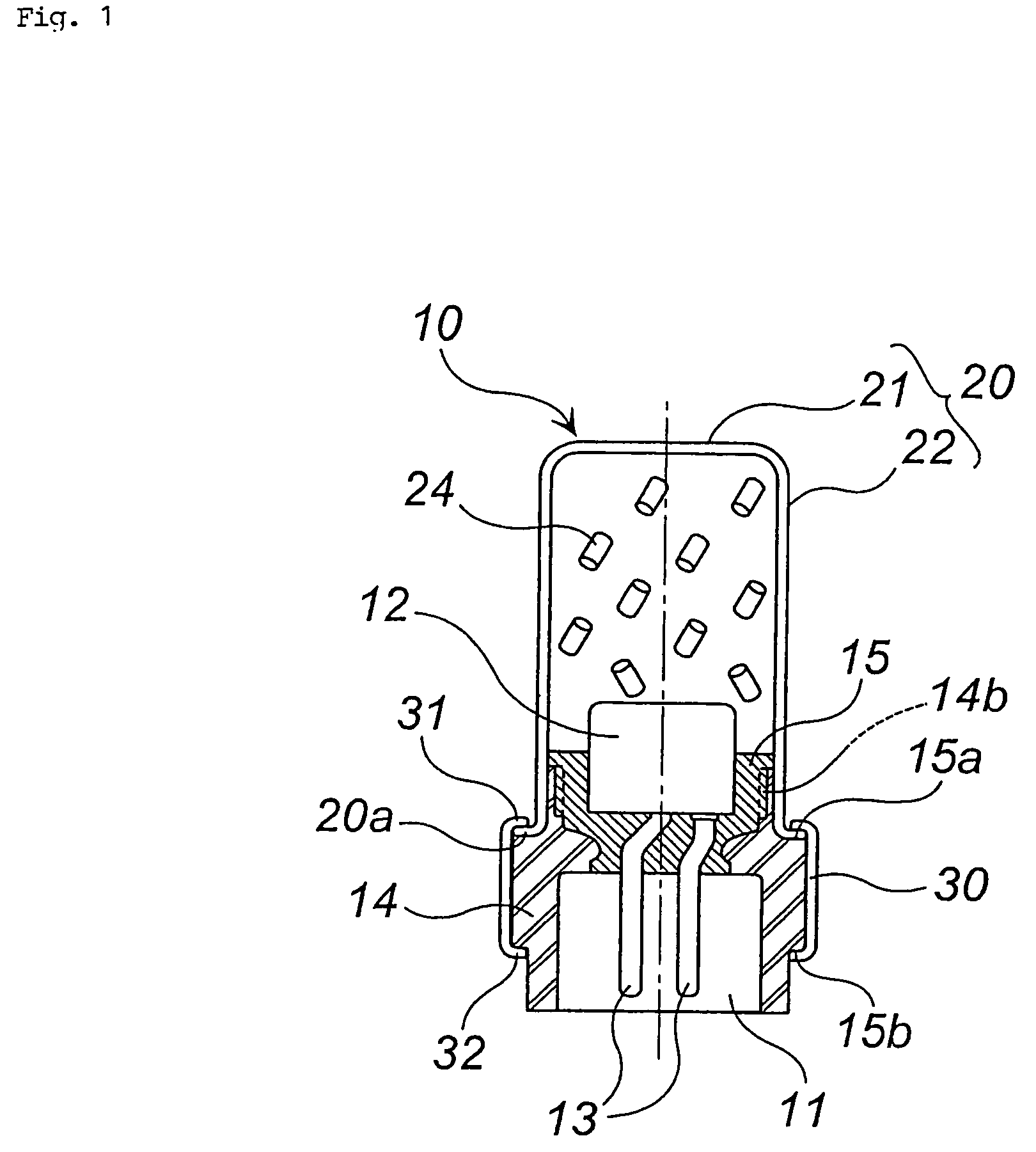
[0046]Embodiment 1 is explained by FIG. 1. FIG. 1 is an axial cross section of a gas generator. The gas generator 10 comprises a combination of an igniter assembly and a cup body 20.
[0047]The igniter assembly contains an igniter main body 12 having an ignition portion to be ignited by an ignition electric current, and an igniter collar 14 of generally cylindrical shape surrounding and holding outside of the igniter main body 12. The igniter collar 14 can be formed of a metal or resin.
[0048]The igniter main body 12 has two electroconductive pins 13 and the vertex becomes an ignition portion. A connector 11 is connected to the electroconductive pins 13, and the igniter main body 12 is connected to a power source via a lead wire extended from the connector 11.
[0049]The igniter collar 14 has a generally cylindrical shape, and it is used for surrounding and holding outside of the igniter main body 12. In the igniter collar 14, an upper flat circumferential edge 15a and an...
embodiment 2
(2) Embodiment 2
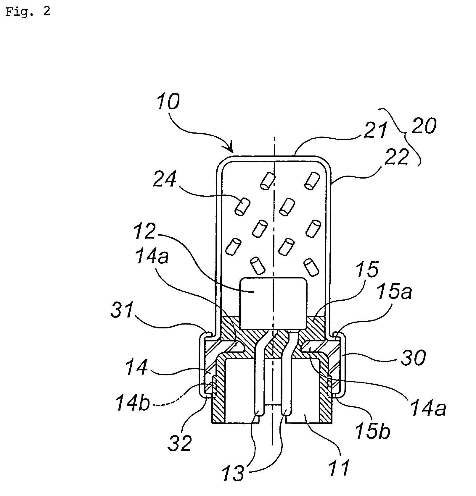
[0058]Embodiment 2 is explained by FIG. 2. FIG. 2 is an axial cross section of a gas generator of another embodiment.
[0059]Since the gas generator 10 of FIG. 2 is completely the same as the gas generator 10 of FIG. 1 except that a shape of the igniter collar 14 is different and necessarily the shape of the resin portion 15 is different, only different portions are explained.
[0060]The igniter collar 14 has a protrusion 14a elongated inwardly compared with that of FIG. 1, and the shape of the resin portion 15 existing between the igniter main body 12 and the igniter collar 14 is different from that of FIG. 1. Furthermore, location of forming the concave portion 14b for rotation prevention of the resin portion 15 shown in FIG. 1 is also different.
[0061]When pouring a melted resin into a space between the igniter main body 12 and the igniter collar 14 and hardening it, the resin shrinks with hardening. At this time, since the resin shrinks in a way of clipping the protru...
embodiment 3
(3) Embodiment 3
[0064]An embodiment of a gas generator for an air bag is explained by FIG. 3. FIG. 3 is an axial cross section of a gas generator for an air bag 100 in which a gas generator 10 shown in FIG. 2 is installed as an ignition means. In stead of the gas generator 10 shown in FIG. 2, the gas generator 10 shown in FIG. 1 can be used.
[0065]In a housing comprising a diffuser shell 101 and a closure shell 102, an inner cylinder 105 is disposed.
[0066]Outside the inner cylinder 105, a circular combustion chamber 110 is arranged and a required amount of gas generating agent 112 is loaded. The gas generating agent 112 is ignited and burnt to generate a combustion gas as an inflation medium of an air bag.
[0067]Inside the inner cylinder 105, the gas generator 10 shown in FIG. 2 as is installed as an ignition means. The gas generator 10 is fastened by abutting the upper end side 31 of the bent portion of the crimp case 30 against a notch portion 106 of the inner cylinder 105, and by c...
PUM
 Abstract
Description
Claims
Application Information
 - R&D
- Intellectual Property
- Life Sciences
- Materials
- Tech Scout
- Unparalleled Data Quality
- Higher Quality Content
- 60% Fewer Hallucinations
Browse by: Latest US Patents, China's latest patents, Technical Efficacy Thesaurus, Application Domain, Technology Topic, Popular Technical Reports.
© 2025 PatSnap. All rights reserved.Legal|Privacy policy|Modern Slavery Act Transparency Statement|Sitemap|About US| Contact US: help@patsnap.com


