Systems and methods for compensating for streaks in images

a technology of electrostatic formation and system, applied in the field of system and method for reducing print defects in electrostatically formed images, can solve the problems of difficulty in adequately calibrating streak defects in a single iteration of the compensation process, and achieve the effect of reducing the effects of halftone spatial period and scanner noise, and allowing changes in printer response to be more easily and/or readily detected

Active Publication Date: 2006-10-24
XEROX CORP
View PDF22 Cites 25 Cited by
  • Summary
  • Abstract
  • Description
  • Claims
  • Application Information

AI Technical Summary

Benefits of technology

[0012]This invention separately provides systems and methods that reduce the effects of halftone spatial period and scanner noise on the compensation process.
[0013]In various exemplary embodiments, systems and methods according to this invention compensate for pixel grid misalignment, by introducing a compensation pattern, which is scanned on an image capture device, such as, for example, a flatbed scanner, that has process control marks and / or alignment marks before and / or after a halftone strip that extends across a process direction. The alignment marks provide alignment between the printer pixel grid and the scanning pixel grid. The process control marks allow changes in the printer response to be more easily and / or readily detected, so that, in response to changes on the process control marks, the selected local tone reproduction curve used for a given pixel location can be changed appropriately.
[0016]In various exemplary embodiments, systems and methods according to this invention reduce noise effects by averaging the toner density measurements of all the pixels in the halftone compensation region identified as being in a specific pixel column by the alignment process.

Problems solved by technology

Furthermore, noise in the scanning and printing process makes it difficult to adequately calibrate the streak defects in a single iteration of the compensation process.

Method used


Image

  • Systems and methods for compensating for streaks in images
  • Systems and methods for compensating for streaks in images
  • Systems and methods for compensating for streaks in images

Examples


Embodiment Construction

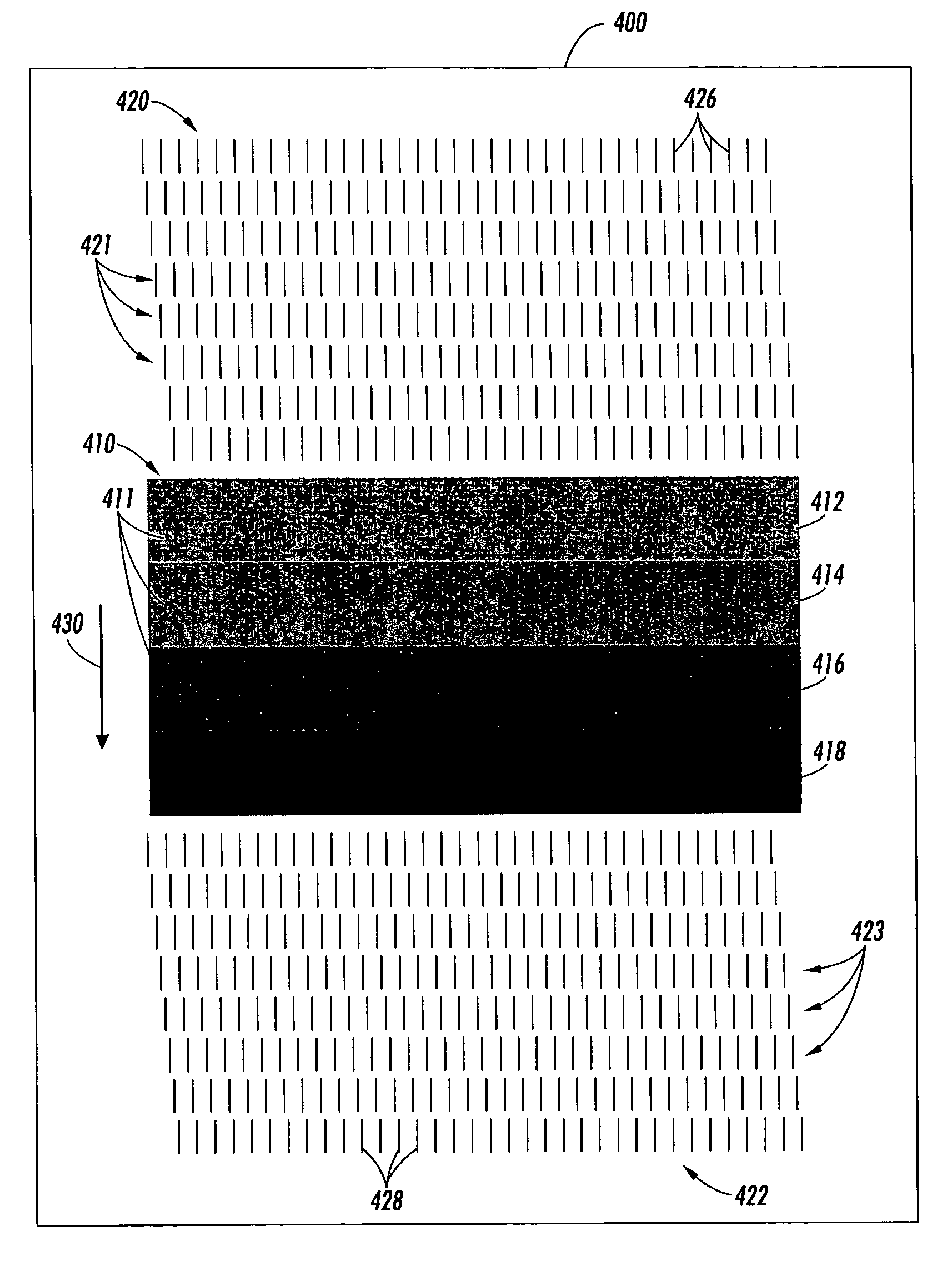
[0035]The compensation technique described herein can be applied to both color and monochrome image forming devices. The following exemplary embodiments are directed to generating and applying compensation parameters to monochrome image forming devices. However, as is well known in the art, color monochrome image forming devices operate by overlaying different color separation layers, i.e., differently colored monochrome images. Accordingly, each color separation layer can be individually compensated for using the techniques described herein. As used herein, the term “gray” indicates the amount of coverage of material between zero and 100% density on the printed surface, although in general this material may be colored any desired color.

[0036]An input gray level is typically an integer between 0 and 255 that is sent to the marking engine from a computer, an input scanner or other image data source. An actual gray level is the response of a sensor measuring the gray level of the prin...


PUM


Abstract

Defects in an image forming system may give rise to visible streaks, or one-dimensional defects in an image that run parallel to the process direction. One known method for compensating for streaks introduces a separate tone reproduction curve for each pixel column in the process direction. A compensation pattern according to this invention has alignment marks before and after a halftone compensation region. The alignment marks provide alignment between the printer pixel grid and a scanning pixel grid. The line width of each alignment mark and the gray level in each pixel column of each gray level portion is measured and analyzed to produce a local tone reproduction curve for each pixel column and associated line width. The line widths of the alignment marks can be remeasured to adjust the local tone reproduction curves to compensate for the streak defect when printing.

Description

BACKGROUND OF THE INVENTION[0001]1. Field of Invention[0002]This invention relates to systems and methods for reducing print defects in electrostatically formed images.[0003]2. Description of Related Art[0004]Defects in the subsystems of a xerographic, electrophotographic or similar image forming system, such as a laser printer, digital copier or the like, may give rise to visible streaks in a printed image. Streaks are primarily one-dimensional defects in an image that run parallel to the process direction. Typical defects might arise from a non-uniform LED imager, contamination of the high voltage elements in a charger, scratches in the photoreceptor surface, etc. In a uniform patch of gray, streaks and bands may appear as a variation in the gray level. In general, “gray” refers to the intensity value of any single color separation layer, whether the toner is black, cyan, magenta, yellow or some other color.[0005]One method of reducing such streaks is to design and manufacture the...

Claims


Application Information

Patent Timeline
Patent Type & Authority Patents(United States)
IPC IPC(8): B41J29/393B41J2/47B41J29/46G03G15/00G03G21/00G06K15/02H04N1/40
CPCG06K15/02G06K15/027H04N1/4015H04N1/4078
Inventor MIZES, HOWARD A.
Owner XEROX CORP
Why Eureka
Try Eureka