Tension-reducing random sprocket

a random sprocket and chain tension technology, applied in the direction of gearing, gearing elements, hoisting equipment, etc., can solve the problems of repeated tension changes, increased chain tension and tension changes, and often generated audible sound frequencies creating undesirable noise, etc., to promote reduced or controlled chain tension and reduce chain noise.

Inactive Publication Date: 2006-10-24
BORGWARNER INC
View PDF98 Cites 41 Cited by
  • Summary
  • Abstract
  • Description
  • Claims
  • Application Information

AI Technical Summary

Benefits of technology

[0017]In accordance with one aspect of the invention, a sprocket is provided that has a root pattern and root radii selected to concentrate the maximum chain tensions at a predetermined order or at multiple predetermined orders relative to the sprocket rotation or another reference, such as, for example, the rotation of a crankshaft in automatic timing chain applications. In this aspect, a sprocket is provided that promotes reduced or controlled chain tensions and may also simultaneously reduce chain noise.
[0020]In accordance with another aspect of the invention, the tooth pattern of the random sprocket may comprise two or more different root radii between adjacent teeth arranged in a predetermined pattern around the circumference of the sprocket effective to reduce the sound frequencies generated as the rollers of the chain engage the sprocket teeth and roots, and the overall tension forces in the chain and sprocket system. In another important aspect of the invention, three different root radii may be arranged in a pattern around the circumference of the sprocket. The use of three different root radii to vary the depth of the spaces between adjacent teeth may further reduce the sound frequencies and overall tension forces exerted on the system.
[0021]The root radii pattern according to the sprocket of another aspect of the invention also may be selected to redistribute the first, second, third, and fourth order tensions imparted to the chain by the sprocket to a fourth order of the sprocket revolution. In yet another aspect of the invention, a sprocket is provided that reduces chain tensions and chain noise, as compared to typical random sprockets designed principally for noise reduction.

Problems solved by technology

However, it has been found that as a chain rotates around a straight sprocket, audible sound frequencies creating undesirable noise are often generated as the pins or rollers connecting the links of the chain contact the sprocket teeth and impact the roots disposed between adjacent teeth of the sprockets.
For example, in automotive timing chain systems, it has been observed from chain tension measurements that the engagement and disengagement of each sprocket tooth and / or root with the chain pins often results in repeating tension changes.
Thus, random sprockets designed principally for noise reduction often cause increases in chain tensions and tension changes as compared to the maximum tensions imparted to the chain by straight sprockets.
However, reducing the pitch order of a sprocket may result in redistributing or concentrating the tensional forces imparted to the chain by the sprocket over the lower orders of the sprocket.
This often results in increased chain tensions corresponding to the lower orders of the random sprocket.
The increased chain tensions at the lower sprocket orders frequently cause the overall maximum chain tension force exerted on the chain and sprocket to increase.
As a consequence, a chain and sprocket system subjected to such tensions typically will experience greater wear and increased opportunities for failure, as well as others adverse effects, due to the concentration of the tensional forces in the lower orders.

Method used


Image

  • Tension-reducing random sprocket
  • Tension-reducing random sprocket
  • Tension-reducing random sprocket

Examples


example 1

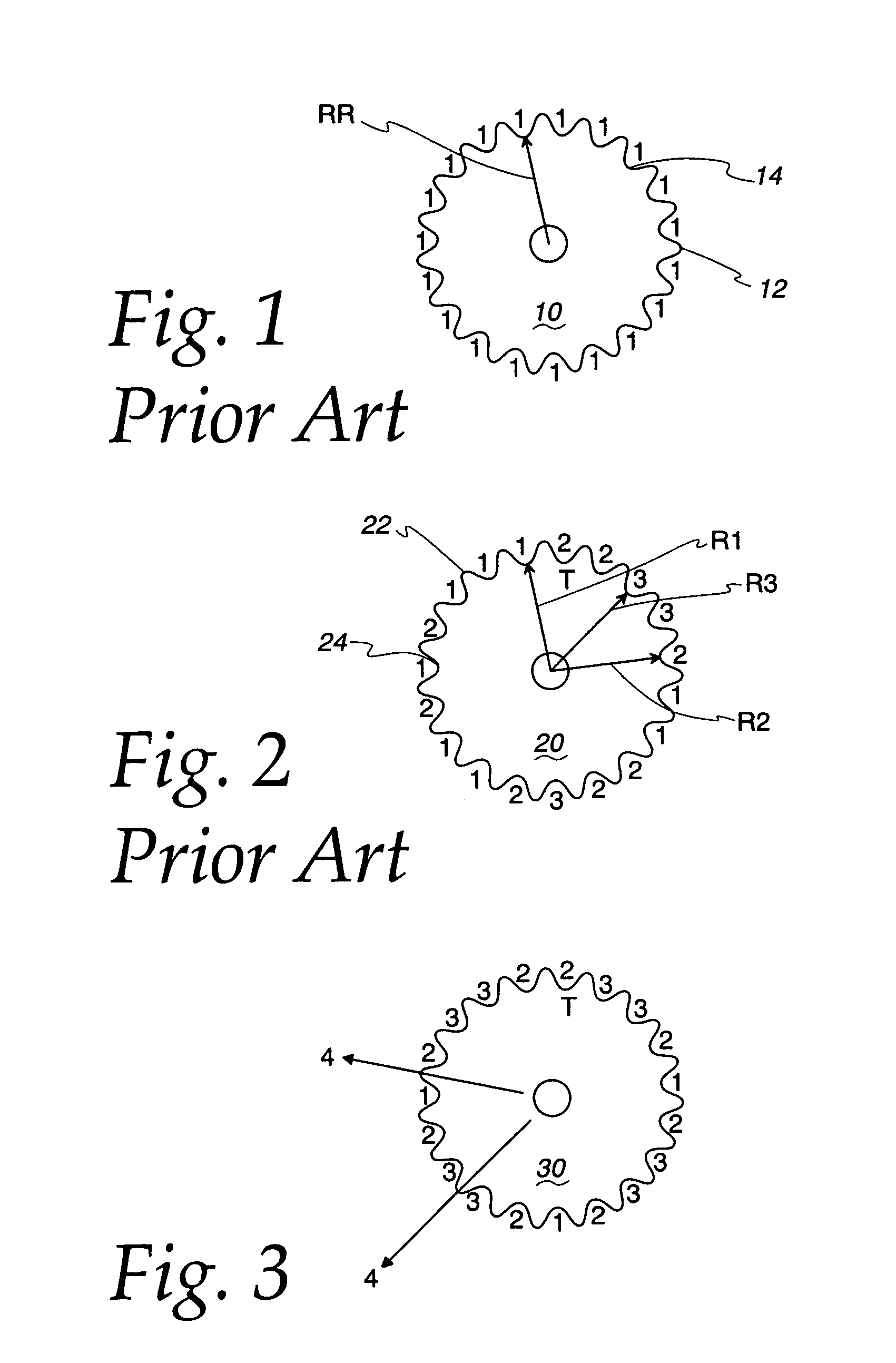
[0040]The random sprocket 20 illustrated in FIG. 2 is designed to reduce noise generated by engagement of the chain 80 with the sprocket 20. The random sprocket 20 is similar to the straight sprocket 10 of FIG. 1, but has three different root radii R1, R2, and R3 and thus three different root depths 1–3. In the sprocket 20 illustrated in FIG. 2, the first root radii R1 is approximately 2.54685 cm, the second root radii R2 is approximately 2.57685 cm, and the third root radii R3 is approximately 2.60685 cm, as measured from the center of the sprocket 20 to the innermost points of the roots 24.

[0041]The root depths 1–3 are arranged in a pattern selected to modulate the engagement frequency between the pins 84 of the chain 80 and roots 24 between adjacent teeth 22 of the sprocket 20 in order to reduce noise generation. As the pins 84 of the chain 80 move between adjacent roots 24 of the sprocket 22, the radial position at which the pins 84 seat varies between a maximum radius, a nomina...

example 2

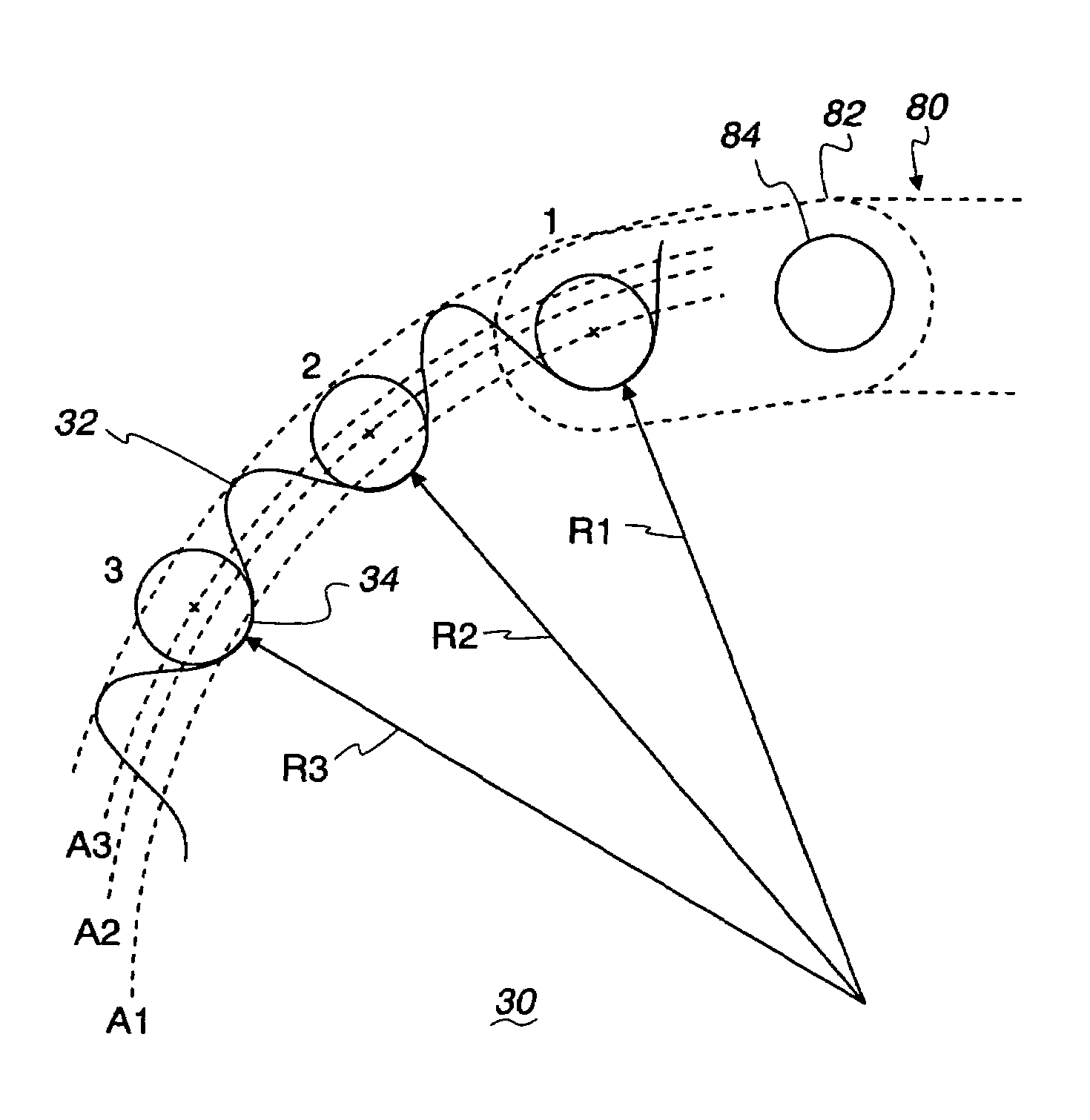
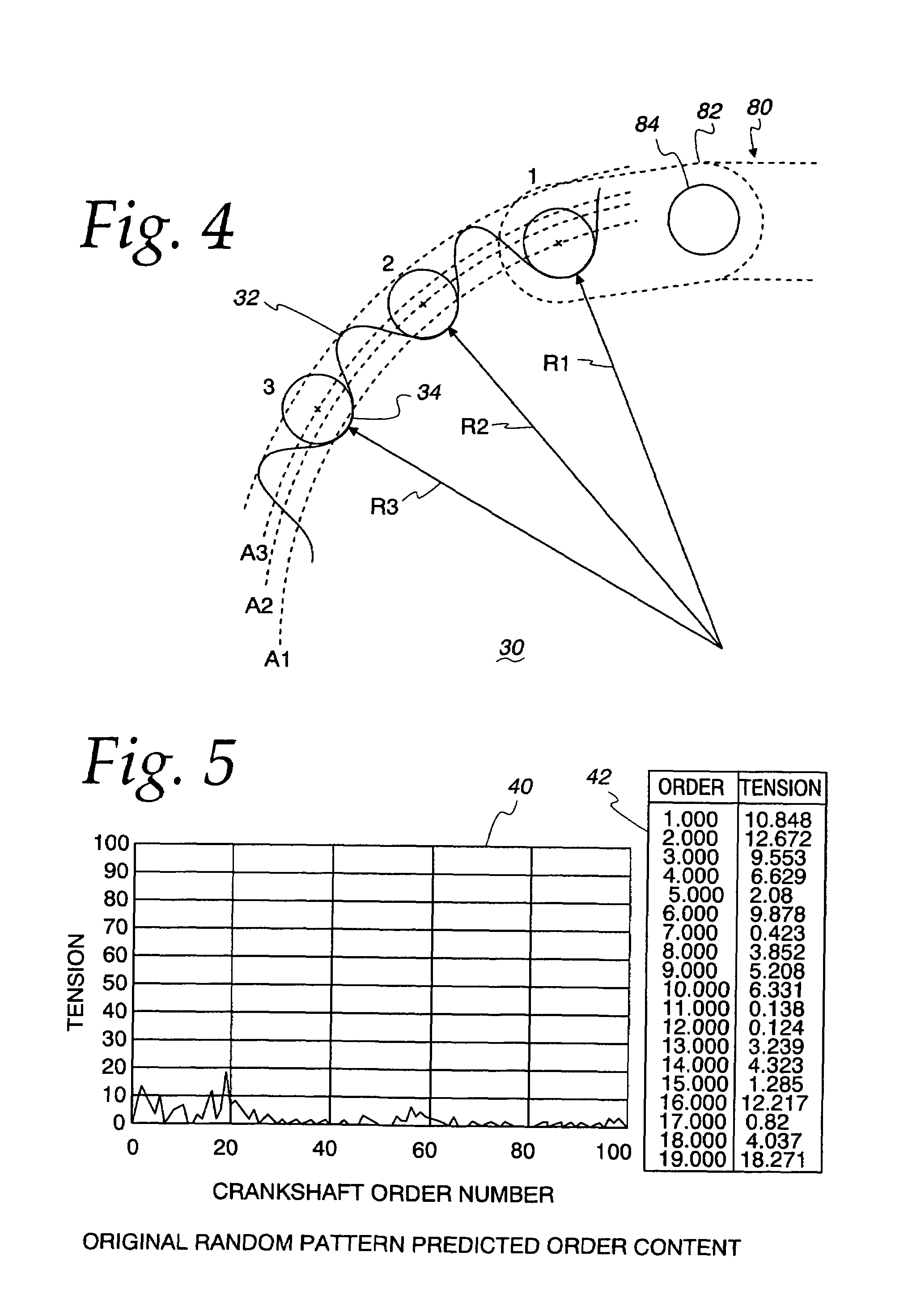
[0053]FIG. 3 illustrates a sprocket 30 according to an aspect of the invention wherein a random sprocket 30 is provided for both redistributing chain tensions at a predetermined sprocket orders and reducing noise generated by engagement of the chain 80 with the sprocket 30. Similar to the straight sprocket 10 of FIG. 1 and the random sprocket 20 designed principally for noise reduction of FIG. 2, the sprocket 30 has a plurality of radially extending teeth 32 disposed about its circumference for engaging the pins 84 of the chain 80. Roots 34 are defined between adjacent teeth 32 for receiving the pins 84 that connect the links 82 of the chain 80.

[0054]The sprocket 30 of FIG. 3 has a maximum root radius R3, a nominal root radius R2, and a minimum root radius R1. As mentioned above, the maximum and minimum root radii are dependent on the link size and pin spacing, the shape of the sprocket teeth, etc. The root pattern of the sprocket 30 of FIG. 3 is different from the root pattern of t...


PUM


Abstract

A sprocket is provided having a plurality of teeth around its circumference. Adjacent teeth are separated by roots each having a root radius defined as the distance between the center of the sprocket and a point along the root closest to the sprocket center in a radial direction. In one aspect of the invention, the sprocket comprises at least two different root radii arranged in a pattern effective to redistribute tensions imparted to a chain by the sprocket at one or more predetermined sprocket orders.

Description

FIELD OF THE INVENTION[0001]The invention relates generally to a sprocket, and particularly to a sprocket for reducing chain tensions.BACKGROUND OF THE INVENTION[0002]Chain and sprocket systems are often used in automotive engine systems to transmit rotational forces between shafts. For example, a sprocket on a driven shaft may be connected via a chain to a sprocket on an idler shaft. In such a chain and sprocket system, rotation of the driven shaft and driven sprocket will cause the rotation of the idler shaft and idler sprocket via the chain. In an automotive engine system, sprockets on the crankshaft may be used, for example, to drive one or more cam shaft sprockets.[0003]The chains used in chain and sprocket systems typically comprise a plurality of intermeshing link plates connected with pins or rollers. The sprockets typically comprise a circular plate having a plurality of teeth disposed around the circumference thereof. Located between adjacent teeth are roots having general...

Claims


Application Information

Patent Timeline
Patent Type & Authority Patents(United States)
IPC IPC(8): F16H55/30F16H7/06
CPCF16H55/30F16H2055/306
Inventor TODD, KEVIN B.
Owner BORGWARNER INC
Why Eureka
Try Eureka