Sub-micron adjustable mount for supporting a component and method

a technology of adjustable mounts and components, applied in the direction of instruments, soldering devices, manufacturing tools, etc., can solve the problems of inability to precisely predict or control the strain of hammering, inevitably relies on some level of trial and error, and the technique introduced by jang is likely, at best, to be time-consuming and at least potentially unreliabl

Inactive Publication Date: 2006-10-24
DEMERS JOSEPH R
View PDF62 Cites 94 Cited by
  • Summary
  • Abstract
  • Description
  • Claims
  • Application Information

AI Technical Summary

Benefits of technology

[0025]In another aspect of the present invention, an apparatus, system and method are described for attaching a workpiece to an electrically conductive support surface using one or more micro welds. A spot welding arrangement is provided including an electrode having an elongated configuration extending to an electrode tip for electrically contacting the workpiece and for passing a welding current between the workpiece and the electrode tip. A welding configuration of the electrode tip is established by exposing the electrode tip to a selected welding environment for use in forming a micro weld having a target set of weld parameters. The workpiece is welded to the support surface using the electrode tip in contact with the workpiece to form the micro weld having the target set of weld parameters by re-exposing the electrode tip to the selected welding environment in a way which maintains the welding configuration of the electrode tip for use in forming an additional micro weld having the target set of weld parameters. In one feature, the electrode tip self-welds to the weld region, at least to a limited extent, in a way which at least partially contributes to maintaining the welding configuration of the electrode tip. In another feature, a force is applied to the electrode to remove the electrode tip from the workpiece, after self-welding to the workpiece, to at least partially maintain the welding configuration of the electrode tip. In still another feature, the electrode tip is resiliently biased against the workpiece through an elongated length such that a flexible characteristic of the elongated length of the electrode cooperates with the resilient biasing force in a way which limits deformation of the electrode tip resulting from contacting the workpiece so as to at least partially contribute to maintaining the welding configuration of the electrode tip.

Problems solved by technology

Unfortunately, it is not possible to precisely predict or control hammering induced strains.
This method, like any method using laser hammering, therefore, inevitably relies on some level of trial and error.
For this reason, the technique introduced by Jang is likely, at best, to be time consuming and is at least potentially unreliable.
The outcome may be a mounting arrangement that exhibits long-term creep with an attendant performance degradation over time.
Unfortunately, however, this implementation is subject to relatively large magnitudes of spring-back upon release of the component.
While spring-back is generally problematic using any form of direct-clamping, it is submitted that weld shift still further exacerbates the spring-back problem since the flexible clip absorbs much of the weld shift in the form of elastic deformation.
In sum, the offending stresses which produce spring-back are difficult to avoid, and unless the mounting clip is extremely rigid, small stresses may lead to large shifts of up to 3–10 microns.
Unfortunately, it is submitted that these more traditional approaches at best are touchy, process-sensitive and potentially time consuming.
At the same time, this method attempts to cope with the spring-back problem, described above, particularly complicated through the use of a flexible clip.
This method raises concerns in requiring a bulky, rigid clamp, as well as a rigid component or clip (typically, the part to be mounted consists of solid machined construction).
Unfortunately, it is submitted that hard-clamping techniques, in any of the described varieties, encounter significant difficulties in attempting to produce reliable positioning (as contemplated herein, to ±0.1 um tolerance).
Unclamping unavoidably releases residual forces, thereby causing at least some undesired spring-back such that this problem remains unresolved.
This approach, however, shares a disadvantage with direct-clamping.
While spring-back can be compensated for somewhat predictably by intentionally overshooting the desired position, it is submitted to be extremely difficult to compensate to within 0.1 um tolerances.
Still considering Webjorn, while the described support structure and technique should be generally effective in achieving precision alignment, it is submitted that important disadvantages accompany its use.
It is submitted that the very length of the elongated main body along the light path and which is required in order to achieve precision movement, already renders the device far too long for many applications.
More importantly, any bending or other such distortion, for example, due to thermal stresses or mounting, in the overall package which houses the Webjorn arrangement will result in reduced optical coupling.
It is herein recognized that the length of the main body, even without an increase therein for purposes of adjustment enhancement, is likely to disadvantageously require an overall package outline that is stiffer and bulkier (and therefore larger and more costly) than would traditionally be required.
That is, an increase in length still further complicates matters with respect to package bending and outline.
Moreover, it is submitted that the sole structure described in detail by Wolfgang, a tripod, is not well-suited for linear stacking along an optical path for purposes of producing a compact assembly.
In this regard, it is noted that this disadvantage is shared with Webjorn since the latter requires the use of an elongated main body.

Method used


Image

  • Sub-micron adjustable mount for supporting a component and method
  • Sub-micron adjustable mount for supporting a component and method
  • Sub-micron adjustable mount for supporting a component and method

Examples


Embodiment Construction

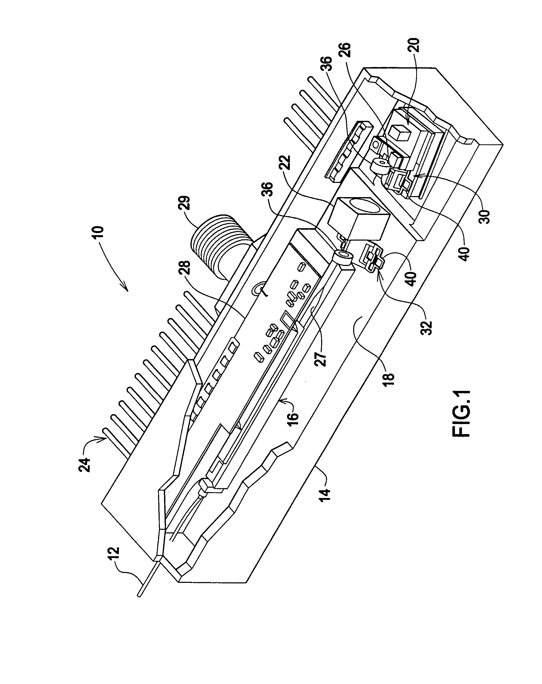
[0107]Turning now to the figures wherein like components are indicated by like reference numbers throughout the various figures, attention is immediately directed to FIG. 1 which illustrates an optical assembly generally indicated by the reference number 10 and produced in accordance with the present invention. It is noted that the figures are not to scale, being enlarged for purposes of illustrative clarity. Further, it is to be understood that naming conventions developed with reference to one or more of the figures such as “upper” and “lower” are adopted in this description and the appended claims for descriptive purposes only and are in no way intended as being limited in view of varying device orientations. FIG. 1 is a partial cutaway view of optical assembly 10 illustrating its structure. In the present example, optical assembly 10 comprises a transmitter module which is configured for modulating laser light and thereafter injecting the modulated light into an optical fiber 12...


PUM

PropertyMeasurementUnit
diameteraaaaaaaaaa
diameteraaaaaaaaaa
thickaaaaaaaaaa

Abstract

An arrangement is provided including an electrode extending to an electrode tip for contacting a workpiece. A welding configuration of the electrode tip is established by exposing the electrode tip to a selected welding environment for use in forming a weld having a target set of weld parameters. An electrode passage is defined in a biasing force arrangement supporting at least a portion of the length of an elongated, flexible electrode and to limit lateral movement sufficient to transfer at least a portion of a resilient force to the electrode tip so that the tip resiliently contacts the weld region. The electrode passage limits induced lateral flexing to an extent which transfers an amount of the resilient force to the first end portion of the electrode that is sufficient to provide for formation of a weld between the support arrangement and the workpiece.

Description

RELATED APPLICATIONS[0001]The present application is a Continuation-in-Part of U.S. application Ser. No. 10 / 394,326, filed on Mar. 20, 2003, which is a Continuation-in-Part of U.S. application Ser. No. 10 / 150,183, filed on May 17, 2002 which itself claims priority from U.S. Provisional Patent Application Ser. No. 60 / 361,237, filed on Feb. 28, 2002, all of which applications are incorporated herein by reference.BACKGROUND OF THE INVENTION[0002]The present invention is related generally to the field of optical component alignment in an optical assembly and, more particularly, to arrangements and an associated method for aligning and fixedly supporting an optical component, as part of an optical assembly, with high precision in relation to an optical path.[0003]The prior art appears to be replete with approaches for supporting optical components in an aligned condition, for example, within an optical package. While it is admitted that a great number of these approaches are at least gen...

Claims


Application Information

Patent Timeline
Patent Type & Authority Patents(United States)
IPC IPC(8): B23K11/10B23K11/30B23K35/02G02B7/00
CPCG02B7/00
Inventor DEMERS, JOSEPH RWOODARD, NATHANCHEN, CHIEN-CHUNG
Owner DEMERS JOSEPH R
Why Eureka
Try Eureka