Stopping noise reduction circuit for start motor using resistor

a technology of stopping noise reduction and resistor, which is applied in the direction of motor/generator/converter stopper, engine starter, dynamo-electric converter control, etc., can solve the problems of shortening the endurance life of the brush, prolonging the time taken to conduct the induced current to ground, and prolonging the stopping time of the rotator of the start motor b>2/b>, so as to achieve maximum reduction of stopping noise, improve the reduction effect of stopping nois

Active Publication Date: 2006-10-24
VALEO ELECTRICAL SYST KOREA
View PDF2 Cites 4 Cited by
  • Summary
  • Abstract
  • Description
  • Claims
  • Application Information

AI Technical Summary

Benefits of technology

[0011]The invention is intended to solve the disadvantages of the general stopping noise reduction circuit for the start motor and improve the reduction effects of the stopping noise. It is, therefore, a primary object of the present invention to provide a stopping noise reduction circuit for a start motor using a resistor that is capable of maximally reducing a stopping noise by freely adjusting a stopping time of a rotator in the start motor by connecting the resistor to two terminals separately arranged inside a solenoid such that a current induced by the rotator or rotor of the start motor is conducted to ground by way of the resistor after the two terminals are coupled via a movement contact upon a turning off of a key switch.
[0012]In accordance with the present invention, there is provided a stopping noise reduction circuit for a start motor comprising a battery for generating a power to drive the start motor, a key switch for controlling an on / off of the power supply from the battery, and a solenoid having a permanent magnet, P and H coils, and a movement contact to drive the start motor, the circuit comprising: a B1 terminal grounded inside the solenoid; an M1 terminal connected to an M terminal of the start motor; and a resistor is coupled with the B1 or M1 terminal, wherein, upon a turning off of the key switch, the movement contact of the solenoid is connected to the B1 and M1 terminals such that more induced current than an induced current flowing into the P and H coils inside the solenoid, in a current induced by a rotator of the start motor, is is conducted to ground via the resistor within a short time.

Problems solved by technology

In the prior art circuit, however, the stopping time of the rotator of the start motor 2 is lengthy, that is, the time taken to conduct the induced current to ground is prolonged.
Due to this reason, the stopping noise of the rotator, that is, mechanical and electrical noise, which seems to be not revealed or issued since it is involved in mechanical friction noise (such as friction tone of pinion and ring gear) during the start-up operation, is produced as high frequency component for a long time after a completion of the start-up operation.
In the conventional stopping noise reduction circuit for the start motor, however, the induced current flows into the body from the M terminal, the M1 terminal, and the B1 terminal at a time maximally rapidly, without using any separate resistor, stopping the rotator (rotor) of the start motor 2 within an excessively short time.
For this reason, an abnormal tone occurs by an amplification of the existing stopping noise by a different stopping noise, and a high current flows instantaneously for a short time, which shortens the endurance life span of the brush.

Method used


Image

  • Stopping noise reduction circuit for start motor using resistor
  • Stopping noise reduction circuit for start motor using resistor
  • Stopping noise reduction circuit for start motor using resistor

Examples


Embodiment Construction

[0019]Hereinafter, a structure and an operation of a stopping noise reduction circuit for a start motor using a resistor in accordance with the present invention will be explained in detail with reference to the accompanying drawings.

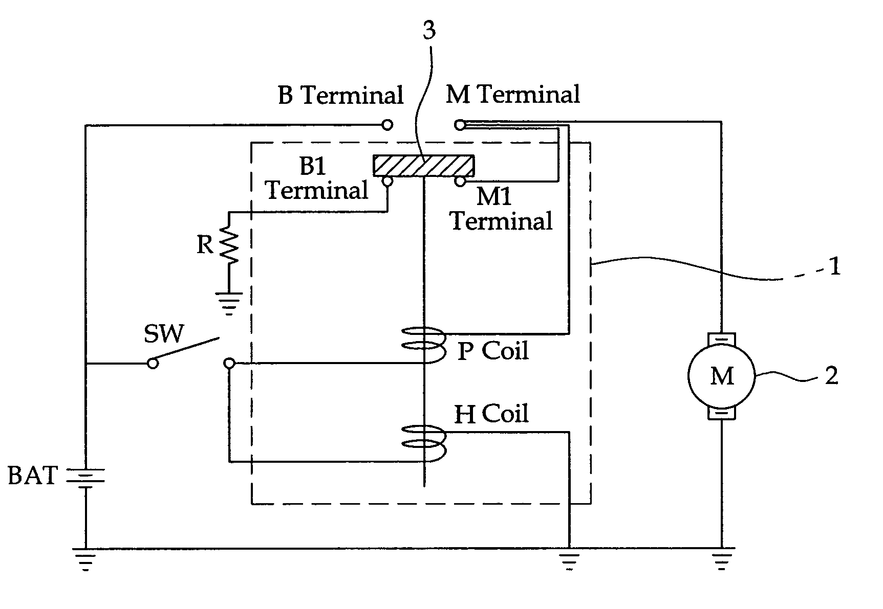
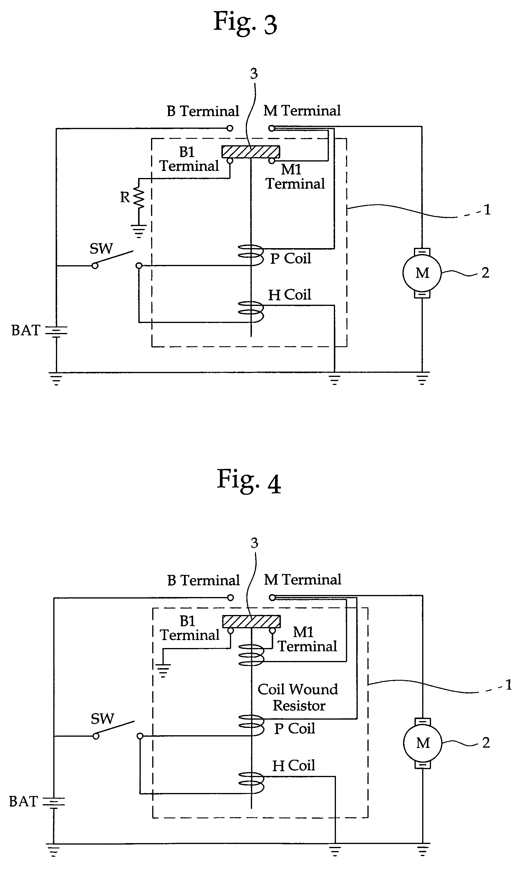
[0020]FIG. 3 is a diagram showing a stopping noise reduction circuit for a start motor employing a resistor in accordance with one embodiment of the present invention. As shown, a resistor with a resistance value less than that of a serial circuit of P and H coils in a solenoid 1 is connected to a B1 terminal, out of two terminals B1 and M1 separately provided in the solenoid 1.

[0021]Specifically, the stopping noise reduction circuit for the start motor in accordance with one embodiment of the present invention comprises a battery BAT for supplying a power to drive a start motor 2, a key switch SW for controlling an on / off of the power supply from the battery BAT, and a solenoid 1 having a permanent magnet, P and H coils for driving the start motor 2.

[0...


PUM


Abstract

A stopping noise reduction circuit for a start motor comprises a battery generating a power supply to drive the start motor, a key switch for controlling an on / off of the power supply, a solenoid having a permanent magnet, P and H coils, and a movement contact to drive the start motor, and further comprises a B1 terminal grounded inside the solenoid, an M1 terminal connected to an M terminal of the start motor, and a resistor coupled with the B1 or M1 terminal. In the stopping noise reduction circuit, upon an off condition of the key switch, the movement contact of the solenoid is connected to the B1 and M1 terminals such that more induced current than an induced current flowing into the P and H coils, in a current induced by a rotator of the start motor, flows to ground via the resistor within a short flow time.

Description

BACKGROUND OF THE INVENTION[0001]1. Field of the Invention[0002]The present invention relates to a stopping noise reduction circuit for a start motor using a resistor, and more particularly, to a stopping noise reduction circuit for a start motor using a resistor that is capable of maximally reducing a stopping noise by freely adjusting a stopping time of a rotator (rotor) in the start motor by making that the resistor is connected to two terminals separately arranged inside a solenoid such that a current induced by the rotator of the start motor is conducted to ground by way of the resistor after the two terminals are coupled via a movement contact upon an off operation of a key switch.[0003]2. Description of Related Art[0004]A conventional start motor drive circuit is generally provided with a solenoid 1, a direct current start motor 2 for a start-up of an engine, a battery BAT, and a key switch SW. In this configuration, when a power is supplied from the battery BAT to the soleno...

Claims


Application Information

Patent Timeline
Patent Type & Authority Patents(United States)
IPC IPC(8): H02P1/00
CPCF02N11/0859F02N15/003H02P1/021H02P3/12F02N11/087H02P3/08
Inventor KIM, CHANG-ILKIM, JI-GONPARK, SOON-SIKAHN, HYUN-CHEUL
Owner VALEO ELECTRICAL SYST KOREA
Why Eureka
Try Eureka