Antenna module and electronic apparatus having the same

a technology of electronic equipment and antenna module, which is applied in the structure of resonant antennas, particular array feeding systems, radiating elements, etc., can solve the problems of deterioration of signal loss and deterioration characteristics of antenna modules, the difficulty of preparing the corresponding space on wireless electronic equipment, and the miniaturization and multifunctionality of antenna modules, so as to improve the degree of freedom of installation structure, increase the space utilization of set, and minimize space

Inactive Publication Date: 2006-10-24
SAMSUNG ELECTRO MECHANICS CO LTD
View PDF14 Cites 14 Cited by
  • Summary
  • Abstract
  • Description
  • Claims
  • Application Information

AI Technical Summary

Benefits of technology

[0016]Therefore, the present invention has been made in view of the above problems, and it is an object of the present invention to provide an antenna module, which minimizes a space, in an electronic apparatus set, occupied thereby without changing characteristics thereof, improves a degree of freedom of the installation structure thereof to increase the space utilization of the set, and achieves miniaturization and multi-functionality of electronic apparatuses, and an electronic apparatus having the antenna module.

Problems solved by technology

It is difficult to prepare the corresponding space on wireless electronic apparatuses, which require miniaturization and multi-functionality.
When the waveguide 24 is vertically folded to be installed in a wireless electronic apparatus after the above antenna module is manufactured, the impedance of the waveguide 24 of the antenna module is changed, thereby causing signal loss and deteriorating characteristics of the antenna module.

Method used


Image

  • Antenna module and electronic apparatus having the same
  • Antenna module and electronic apparatus having the same
  • Antenna module and electronic apparatus having the same

Examples


Embodiment Construction

[0031]Now, preferred embodiments of the present invention will be described in detail with reference to the annexed drawings.

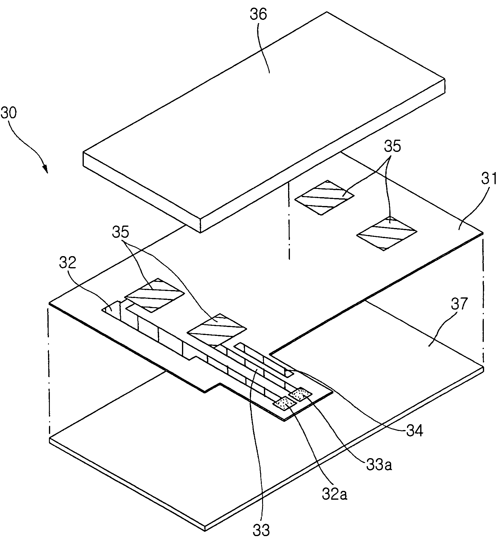
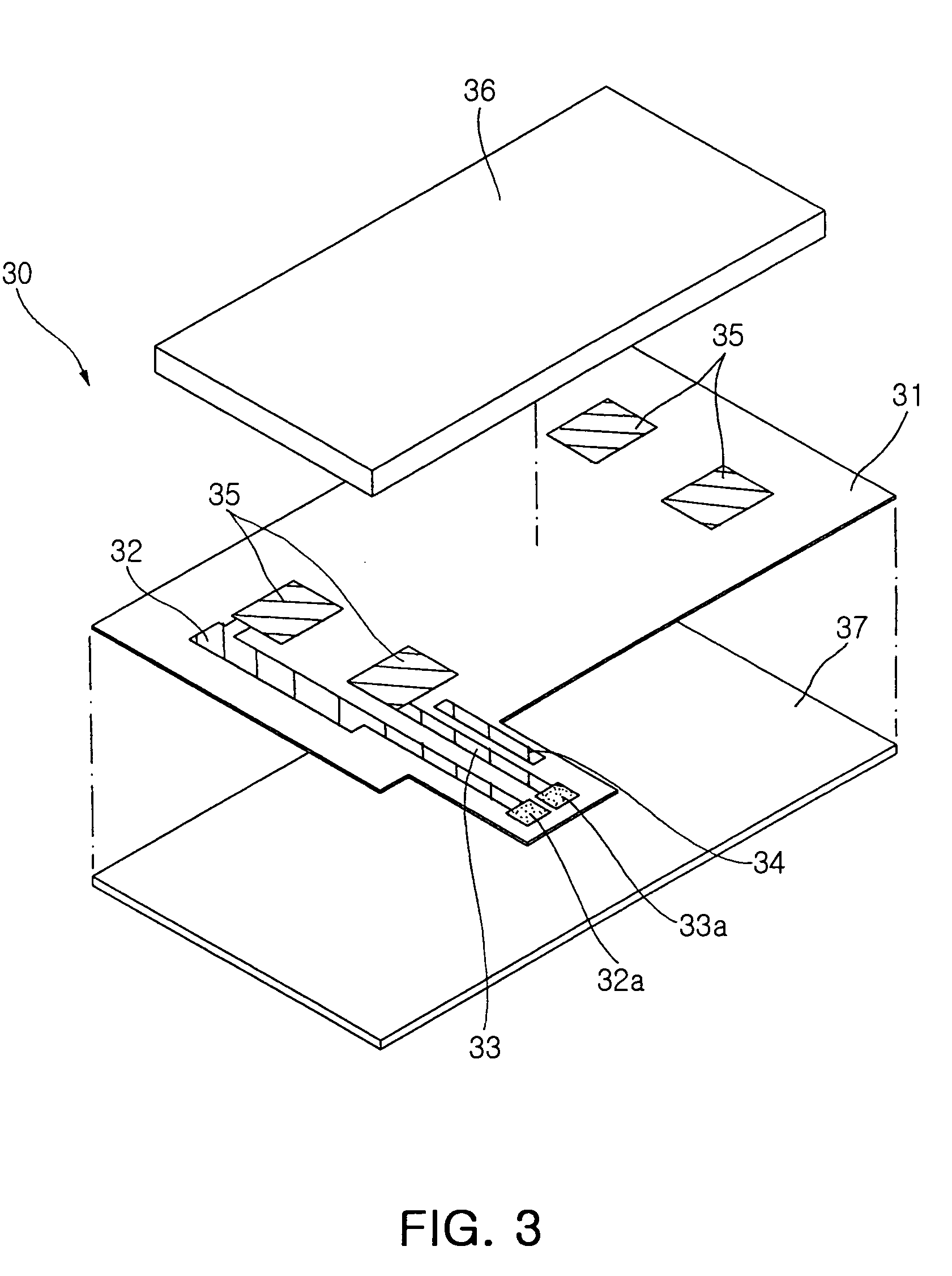
[0032]FIG. 3 is an exploded perspective view illustrating the overall constitution of an antenna module in accordance with the present invention.

[0033]With reference to FIG. 3, the antenna module 30 of the present invention comprises a PCB (printed circuit board) 31 made of nonconductive material having flexibility, a ground line 32 formed on the PCB 31 and made of conductive material for grounding an antenna element 36, a feeder line 33 formed at a designated position of the PCB 31 and made of conductive material for supplying current to the antenna element 36, a passive line 34 formed in parallel with the feeder line 33 and not connected to a ground or signal terminal for adjusting impedance by the electric coupling with the feeder line 33, a plurality of bonding pads 35 formed at a position, for mounting the antenna element 36, of the PCB 31 and connected t...


PUM


Abstract

An antenna module, which minimizes a space, in an electronic apparatus set, occupied thereby without changing characteristics thereof, improves a degree of freedom of the installation structure thereof to increase the space utilization of the set, and achieves miniaturization and multi-functionality of electronic apparatuses, and an electronic apparatus having the antenna module. The antenna module includes a PCB (printed circuit board) made of nonconductive material having flexibility; an antenna element mounted at a designated position of the upper surface of the PCB; a ground line formed on the PCB so that the ground line is connected to a ground terminal of the antenna element, and provided with a joint portion formed at one end thereof; a feeder line formed on the PCB so that the feeder line is connected to a signal terminal of the antenna element, and provided with a joint portion formed at one end thereof; and a passive line, having a designated length, formed on the PCB in parallel with the feeder line. The joint portions of the ground line and the feeder line are bonded to designated positions of a set of the wireless electronic apparatus, and a portion of the antenna module having the antenna element mounted on the PCB is located outside the set.

Description

RELATED INVENTION[0001]The present application is based on, and claims priority from, Korean Application Number 2004-70767, filed Sep. 6, 2004, the disclosure of which is incorporated by reference herein in its entirety.BACKGROUND OF THE INVENTION[0002]1. Field of the Invention[0003]The present invention relates to an antenna module installed on an electronic apparatus having a wireless communication function, and more particularly to an antenna module, which minimizes a space, in an electronic apparatus set, occupied thereby, improves a degree of freedom of the installation structure thereof to increase the space utilization of the set, and achieves miniaturization and multi-functionality of electronic apparatuses, and an electronic apparatus having the antenna module.[0004]2. Description of the Related Art[0005]In order to meet the recent development of semiconductor and communication technique, electronic apparatuses having a wireless communication function for improving mobility...

Claims


Application Information

Patent Timeline
Patent Type & Authority Patents(United States)
IPC IPC(8): H01Q1/24H01Q1/38H01Q9/04H01Q21/00
CPCH01Q1/243H01Q1/38H01Q9/0421H01Q21/0025H01Q9/0442H01Q23/00
Inventor KIM, HYUN HAKKIM, CHUL HOSEO, JEONG SIKPARK, II HWAN
Owner SAMSUNG ELECTRO MECHANICS CO LTD
Why Eureka
Try Eureka