Motor drive circuit with reduced coil crosstalk in a feedback signal indicative of mirror motion in light scanning arrangements

a technology of motor drive and feedback signal, which is applied in the direction of instruments, sensing record carriers, computing, etc., can solve the problems of motor oscillation, impairing motor malfunction detection, and inability to achieve magnetic coupling or crosstalk between the drive and the feedback coil, so as to improve the accuracy of the feedback signal and enhance the performance of the image projector or the reader

Active Publication Date: 2006-10-24
SYMBOL TECH LLC
View PDF2 Cites 10 Cited by
  • Summary
  • Abstract
  • Description
  • Claims
  • Application Information

AI Technical Summary

Benefits of technology

[0019]In accordance with this invention, cancellation circuitry for cross-coupled signals is unnecessary. Accuracy of the feedback signal is improved. The feedback signal has no phase delays. There are no annoying sounds related to transformer coupling between coils. The entire circuitry for monitoring mirror motion can be implemented in an application specific integrated circuit (ASIC).
[0020]In brief, the crosstalk-reduced feedback signal is an accurate representation of motor position and velocity and, hence, of beam position. The crosstalk-reduced feedback signal is not corrupted due to signal feedthrough between the drive and feedback coils. Performance of the image projector or the reader is enhanced.

Problems solved by technology

Although generally satisfactory for its intended purpose, the use of the feedback coil for monitoring for drive failure, for driving the drive motor, and for generating the SOS signal causes problems.
There is undesirable magnetic coupling or crosstalk between the drive and feedback coils.
Without such filtering, the loop would oscillate based on feedback through the coils, thereby impairing motor malfunction detection.
The filtering also changes the frequency of the electromechanical system, thereby causing the motor to oscillate off its natural or resonant frequency, and thereby impairing the drive efficiency.
As in the case of readers, at least one of these scan mirrors is oscillated by a drive which includes a motor having feedback and drive coils, as described above, with their attendant problems of cross-coupled signals, extra hardware, phase delays and annoying sounds.
Crosstalk is a more severe problem in image projectors, because the motion or velocity of the scan mirror and, hence, of each scan line swept by the scan mirror must be very highly controlled to be a constant value for both right-to-left and left-to-right scan lines.

Method used


Image

  • Motor drive circuit with reduced coil crosstalk in a feedback signal indicative of mirror motion in light scanning arrangements
  • Motor drive circuit with reduced coil crosstalk in a feedback signal indicative of mirror motion in light scanning arrangements
  • Motor drive circuit with reduced coil crosstalk in a feedback signal indicative of mirror motion in light scanning arrangements

Examples


Embodiment Construction

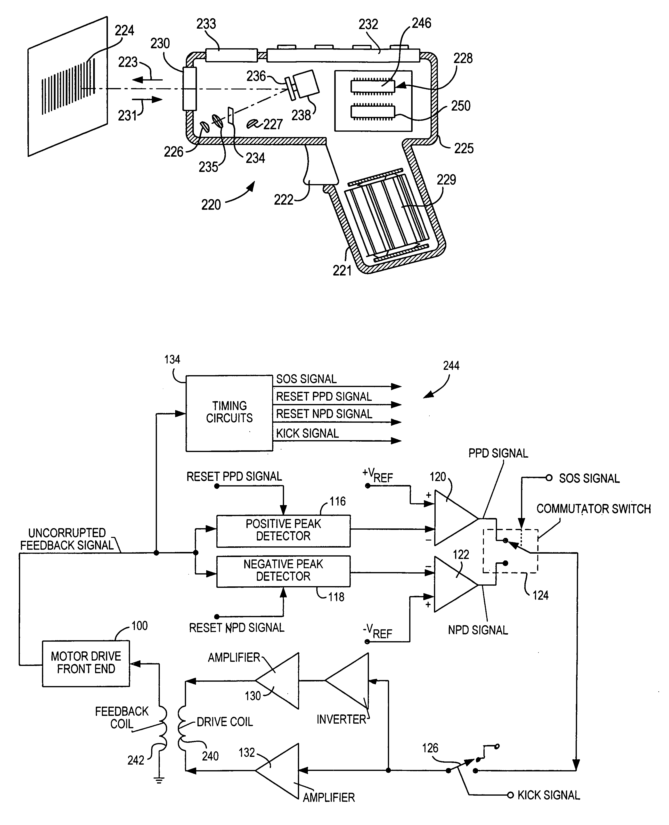
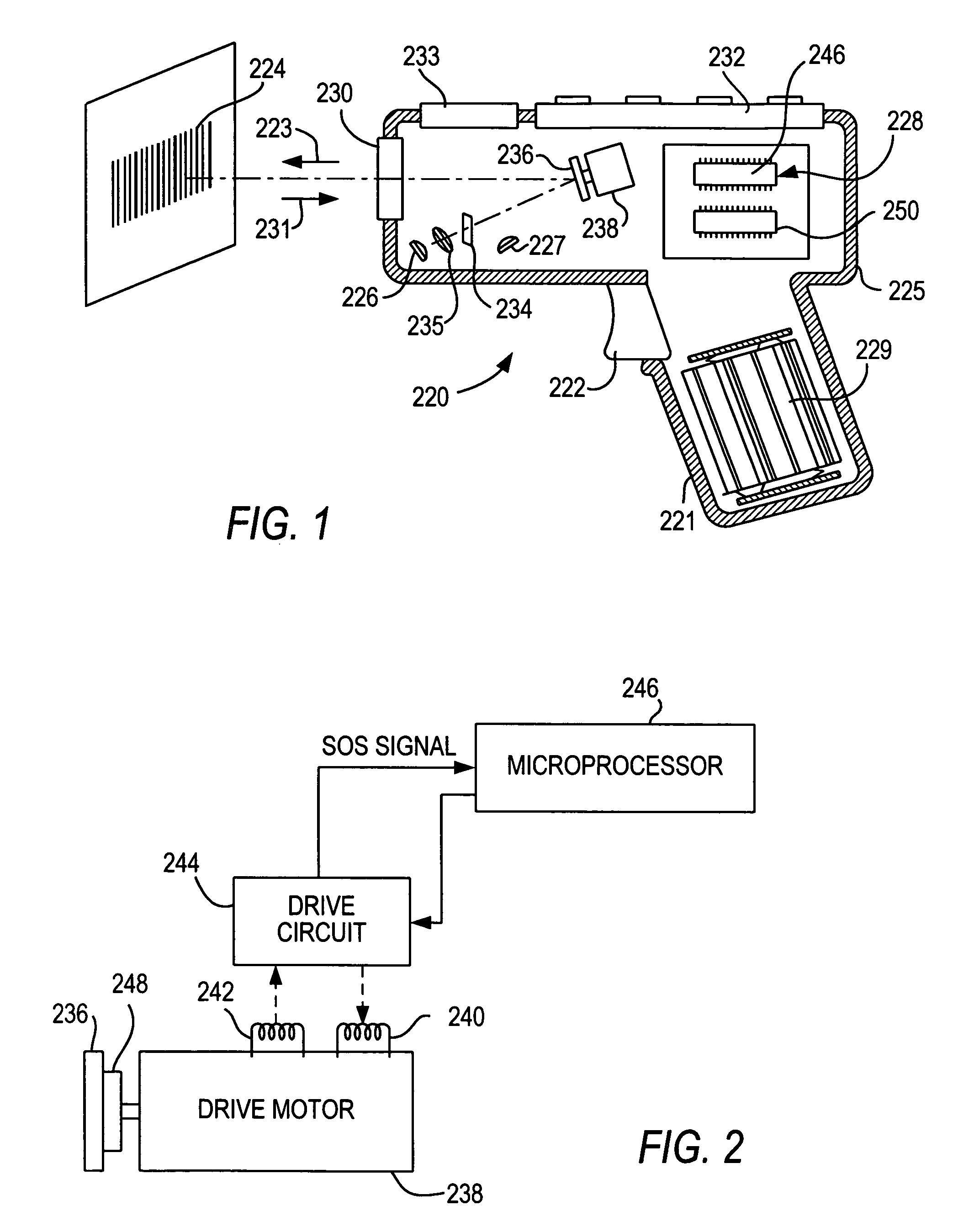
[0028]Reference numeral 220 in FIG. 1 identifies an electro-optical reader for electro-optically reading indicia, such as bar code symbol 224, located in a range of working distances therefrom. The reader 220 has a pistol grip handle 221 and a manually actuatable trigger 222 which, when depressed, enables a light beam 223 to be directed at the symbol 224. The reader 220 includes a housing 225 in which a light source 226, a light detector 227, signal processing circuitry 228, and a battery pack 229 are accommodated. A light-transmissive window 230 at a front of the housing enables the light beam 223 to exit the housing, and allows light 231 scattered off the symbol to enter the housing. A keyboard 232 and a display 233 may advantageously be provided on a top wall of the housing for ready access thereto.

[0029]In use, an operator holding the handle 221 aims the housing at the symbol and depresses the trigger. The light source 226 emits a light beam which is optically modified and focus...


PUM


Abstract

Crosstalk between a drive coil and a feedback coil is eliminated by a motor drive circuit operative for generating the drive coil as a square wave, and by removing the crosstalk which occurs at zero transitions of a feedback signal. The drive coil is used to oscillate a scan mirror employed in an image projection arrangement or an electro-optical reader.

Description

CROSS. REFERENCE TO RELATED APPLICATION[0001]This application claims the benefit of U.S. Provisional Patent Application Ser. No. 60 / 716,302, filed Sep. 12, 2005, commonly assigned herewith.BACKGROUND OF THE INVENTION[0002]1. Field of the Invention[0003]The present invention generally relates to monitoring the motion of a scan mirror employed for sweeping a light beam in electro-optical readers for reading indicia such as bar code symbols, or in image projectors for displaying images and, more particularly, to a motor drive circuit with reduced coil crosstalk in a feedback signal indicative of such mirror motion.[0004]2. Description of the Related Art[0005]Electro-optical readers are well known in the art for electro-optically transforming a spatial pattern of graphic indicia, known as a symbol, into a time-varying electrical signal which is then decoded into data. Typically, a light beam generated from a light source is focused by a lens along an optical path toward a target that in...

Claims


Application Information

Patent Timeline
Patent Type & Authority Patents(United States)
IPC IPC(8): G02B26/08
CPCG06K7/10643G06K2207/1016
Inventor GIEBEL, JAMESDIFAZIO, COSTANZOWEITZNER, MARK A.
Owner SYMBOL TECH LLC
Why Eureka
Try Eureka