
System for determining and regulating EGR (Exhaust Gas Recirculation) mass flow and use method thereof

A mass flow and EGR valve technology, which is applied in the system field of determining and adjusting EGR mass flow, can solve the problems of high cost and complicated measurement methods, and achieve the effects of occupying less space, simplifying measurement methods, and reducing application costs

Active Publication Date: 2014-05-07
DONGFENG COMML VEHICLE CO LTD
View PDF7 Cites 5 Cited by
  • Summary
  • Abstract
  • Description
  • Claims
  • Application Information

AI Technical Summary

Problems solved by technology

[0006] The purpose of the present invention is to overcome the problems of relatively high cost and relatively complicated measurement methods in the prior art, and provide a system for determining and adjusting EGR mass flow rate with relatively low cost and simple measurement and its use method

Method used


Image

  • System for determining and regulating EGR (Exhaust Gas Recirculation) mass flow and use method thereof
  • System for determining and regulating EGR (Exhaust Gas Recirculation) mass flow and use method thereof

Examples


Embodiment 1

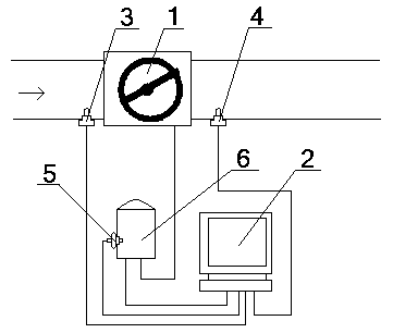
[0057] see figure 1 , figure 2 , a system for determining and adjusting the EGR mass flow rate, comprising an EGR valve 1 and a processor 2, the EGR valve 1 is a butterfly valve, the processor 2 is an engine electronic control unit, and the EGR valve 1 passes through an EGR valve motor 6 Connected to the output end of the processor 2, the entrance of the EGR valve 1 is provided with a No. 1 sensor 3, the exit of the EGR valve 1 is provided with a No. 2 sensor 4, and the EGR valve motor 6 is provided with an EGR valve position opening Sensor 5, the No. 1 sensor 3 is a temperature and pressure sensor, the No. 2 sensor 4 is a pressure sensor, and the output terminals of the No. 1 sensor 3, No. 2 sensor 4, and EGR valve position opening sensor 5 are all connected to the input of the processor 2 terminal signal connection.

[0058] A method for using the above-mentioned system for determining and adjusting EGR mass flow rate, the method includes the following steps in sequence: ...


PUM


Abstract

The invention provides a system for determining and regulating EGR (Exhaust Gas Recirculation) mass flow. The system comprises an EGR valve and a processor, wherein the EGR valve is connected with the output end of the processor by virtue of an EGR valve motor; the inlet of the EGR valve is provided with a sensor I; the outlet of the EGR valve is provided with a sensor II; the EGR valve motor is provided with a position opening sensor; the sensor I is a temperature and pressure sensor; the sensor II is a pressure sensor; The output ends of the sensor I, the sensor II and the position opening sensor are in signal connection with the input end of the processor. When the system is in use, the flow characteristic curve of the EGR valve is calibrated firstly and then stored into the processor, then the processor is used for calculating real-time EGR mass flow according the real-time data and the flow characteristic curve received by the processor and regulating the opening size of the EGR valve; due to the design, the cost is lowered, and the method is simple, convenient and practical.

Description

technical field [0001] The invention relates to a flow measurement system and its use method, in particular to a system for determining and adjusting EGR mass flow and its use method, which is particularly suitable for reducing costs and simplifying the measurement method. Background technique [0002] In order to protect the living environment of our planet, countries are increasingly advocating the concept of low-carbon and environmentally friendly life. Due to the development of social economy, the engine has become an indispensable force in daily transportation and other aspects. With the increasing number of vehicles, the pollutants emitted by them continue to endanger the surrounding environment. Engine emissions mainly include nitrogen oxides and particulates. Nowadays, the emission regulations of diesel engines in various countries in the world are becoming increasingly stringent, while reducing NOx and soot has become a common problem and challenge we are facing. ...

Claims


Application Information

Patent Timeline
Patent Type & Authority Applications(China)
IPC IPC(8): G01F1/86
Inventor 朱丹丹胡前陈伟建侯立杰
Owner DONGFENG COMML VEHICLE CO LTD
Learn More