
Controllable object remote control and diagnosis apparatus

a remote control and control device technology, applied in the field of remote control and diagnostic devices, can solve the problems of time loss, operator on the user side that does not have the know-how of adjustment, and cannot fully take measures, so as to achieve enhanced safety

Inactive Publication Date: 2006-10-24
YASKAWA DENKI KK
View PDF14 Cites 122 Cited by
  • Summary
  • Abstract
  • Description
  • Claims
  • Application Information

AI Technical Summary

Benefits of technology

[0014]Therefore, it is an object of the invention to provide a remote adjusting and diagnosing apparatus capable of easily carrying out the adjustment of a servo gain of a control object and an inherent adjustment in an application through an analyzing computer provided in a remote place, coping with the request of the adjustment given from a user without a time loss, performing an adjustment required for a large-sized measuring device and executing a failure diagnosis during a normal play-back operation without stopping the line of a factory.

Problems solved by technology

In some cases in which the maintenance, diagnosis and adjustment of a control object including a motor such as a robot, a servo motor or an NC device in the factory of a user in a remote place is to be carried out, conventionally, an operator on the user side cannot fully take measures.
The operator on the user side that does not have the know-how of the adjustment carries a risk in some cases.
Consequently, a time loss is generated.
In some cases, thus, it is hard to bring the measuring device on a physically narrow line.
Moreover, there is a problem in that the line of a factory is to be stopped also when the periodic diagnosis or the failure diagnosis is to be carried out or a large-sized measuring device is to be brought in.
In the case in which the operator is not present, therefore, a countermeasure cannot be taken and a time loss is generated so that any processing cannot be carried out during the play-back operation of the control object and the periodic diagnosis and the failure diagnosis cannot be performed automatically.
For this reason, it is impossible to carry out the periodic diagnosis and the failure diagnosis during the play-back operation to be performed based on a work program created by an operator on the user side.

Method used


Image

  • Controllable object remote control and diagnosis apparatus
  • Controllable object remote control and diagnosis apparatus
  • Controllable object remote control and diagnosis apparatus

Examples


second embodiment

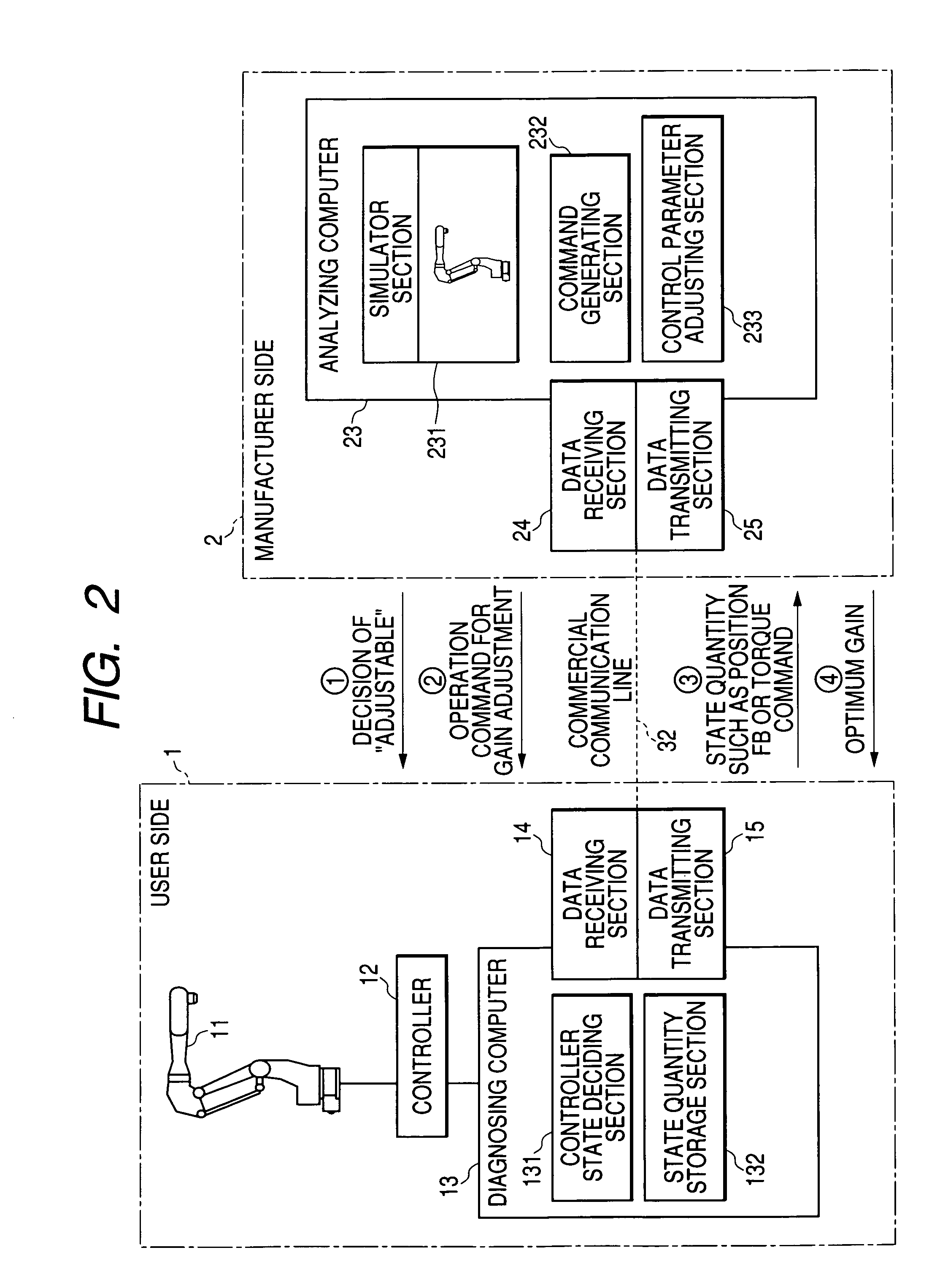
[0069]Next, the invention will be described with reference to FIG. 2.

[0070]As described in the fourth aspect of the invention, the action of each block will be described on the assumption that the servo gain adjustment of a robot 12 is carried out.

(1) Decision of Adjustment Preparation

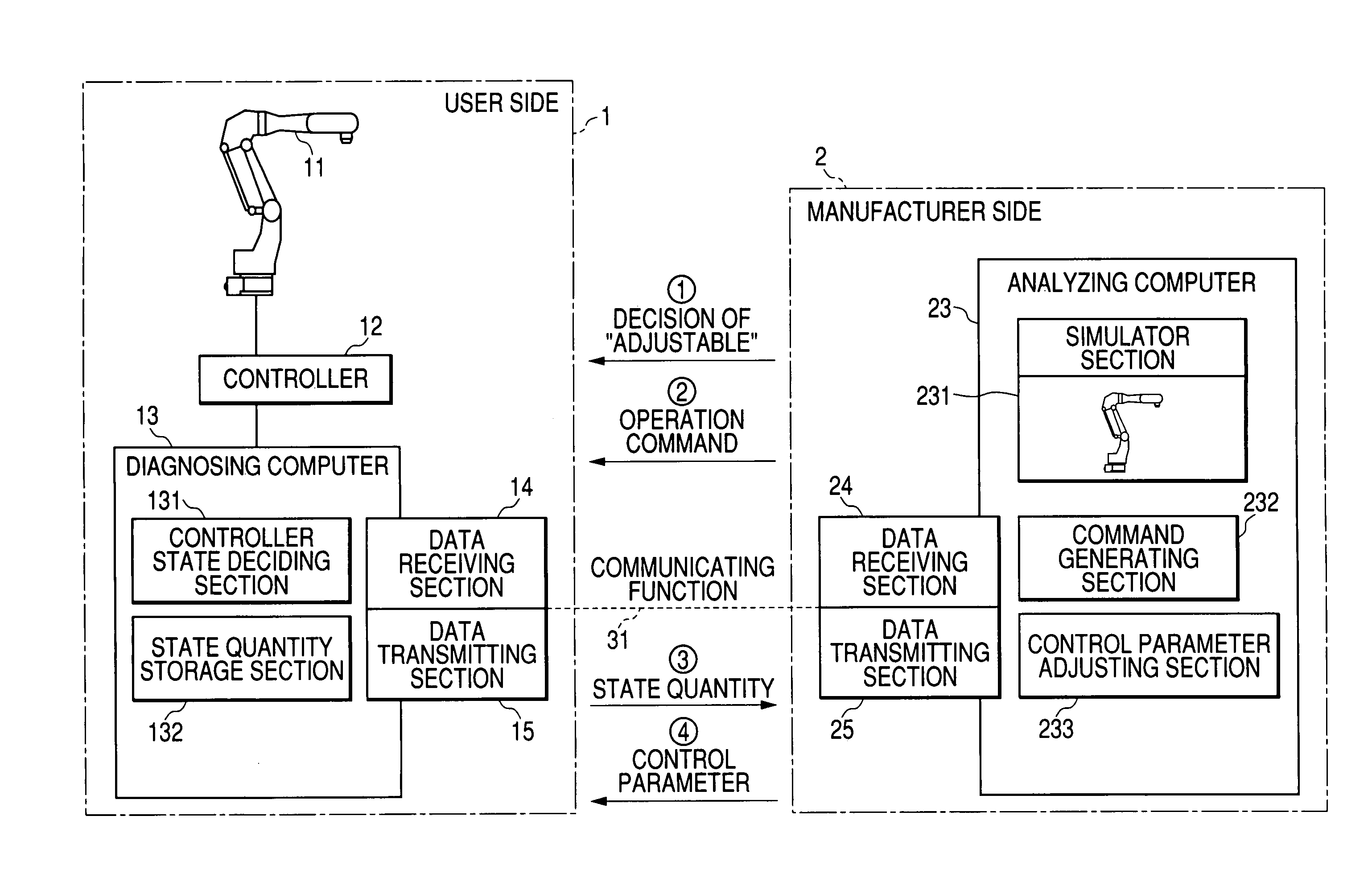
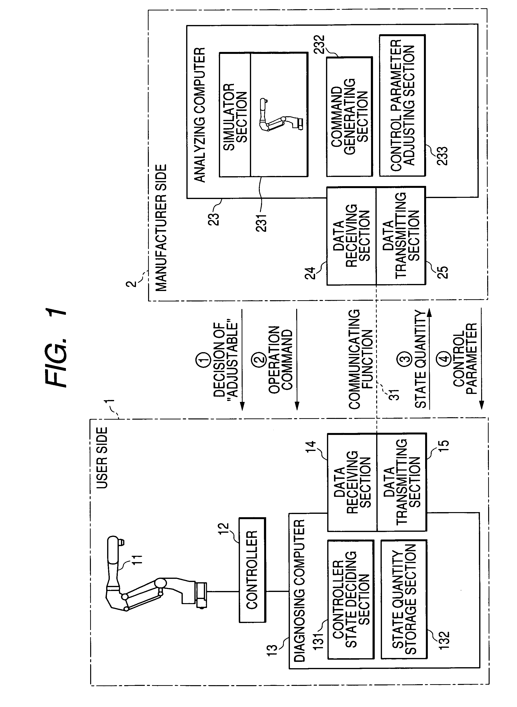
[0071]An operator on a manufacturer side 2 generates a state decision command for adjusting the servo gain of the robot 11 for a diagnosing computer 13 present in a remote place by a command generating section 232 of an analyzing computer 23. The state decision command is transmitted from a data transmitting section 25 to a data receiving section of the diagnosing computer through a commercial communication line 32 such as a telephone circuit ({circle around (1)} in the drawing).

[0072]In the case in which it is decided from the state of the robot 11 connected to a controller 12 that the gain can be adjusted in a controller state deciding section 131 of the diagnosing computer 13, a signal of “servo gai...

third embodiment

[0084]Next, the invention will be described below with reference to FIG. 4.

[0085]As described in the fifth aspect of the invention, the action of each block will be described on the assumption that the welding condition of arc welding to be carried out by a robot is to be adjusted for the adjustment of an inherent condition parameter in an application. The condition parameter of the welding condition includes a welding speed, a welding torch angle and a feeding speed of a welding wire feeding motor.

(1) Acquirement of Work Data

[0086]The condition of the arc welding is greatly varied depending on the shape and material of a work. For this reason, it is necessary to previously limit the condition to some extent. Therefore, the operator on a user side 1 registers the shape and material of the work to be subjected to the arc welding in a controller 12 or a diagnosing computer 13. Data on the shape and material of the work which are thus registered are transmitted from a data transmitting...

fourth embodiment

[0095]Next, the invention will be described with reference to FIG. 5.

[0096]The action of each block will be described on the assumption of the diagnosis and prediction of a failure in a play-back operation. As described in the seventh aspect of the invention, an analyzing computer 23 is constituted by a data transmitting section 25, a data receiving section 24, a simulator section 231, and a failure diagnosing and predicting section 234 for deciding and estimating the presence of the abnormality of the operation of a robot 11 from the operation command and state quantity of the robot 11.

[0097]In the play-back operation of the robot 11, an operation command created by an operator on a user side 1 and the control state quantity of the robot 11 are stored in a state quantity storage section 132 in a specific sampling cycle. At time of the end of the operation or in response to the command sent from the analyzing computer 23, they are transmitted from a data transmitting section 15 of a...


PUM


Abstract

A robot apparatus having a robot and a controller for controlling the robot. The apparatus has a diagnosing computer connected to the controller and acquiring a state quantity of the robot. An analyzing computer is provided remotely from the robot and has a control parameter adjuster for adjusting a control parameter of the robot, and a communicating function of connecting the computers. The state quantity is transmitted to the analyzing computer by the communicating function and a control parameter of the robot is obtained based on the state quantity. The control parameter is transmitted to the controller through the diagnosing computer to control the robot.

Description

TECHNICAL FIELD[0001]The present invention relates to a remote adjusting and diagnosing apparatus for carrying out the adjustment, maintenance and diagnosis of a control object such as a robot, a servo motor or an NC device which is provided in a remote place.BACKGROUND ART[0002]In some cases in which the maintenance, diagnosis and adjustment of a control object including a motor such as a robot, a servo motor or an NC device in the factory of a user in a remote place is to be carried out, conventionally, an operator on the user side cannot fully take measures. For example, it is necessary to newly adjust a servo gain at such a degree that a different load is applied to the control object in some cases. Since the control object oscillates depending on an adjusting method. The operator on the user side that does not have the know-how of the adjustment carries a risk in some cases. For this reason, an operator on the manufacturer side or an operator in a service center on the manufact...

Claims


Application Information

Patent Timeline
IPC IPC(8): G06F19/00B25J13/00B25J9/16G05B19/00G05B19/4063G05B19/418G05B23/02
CPCB25J9/1674G05B19/4063G05B2219/33284G05B2219/33286Y02P90/02Y02P90/80G05B23/02
Inventor NAGATA, HIDEOINOUE, YASUYUKIYASUDA, KEN'ICHIHANDA, HIROYUKI
Owner YASKAWA DENKI KK
Features
  • Generate Ideas
  • Intellectual Property
  • Life Sciences
  • Materials
  • Tech Scout
  • Unparalleled Data Quality
  • Higher Quality Content
  • 60% Fewer Hallucinations
Learn More