Systems and methods for providing backup energy to a load

Inactive Publication Date: 2006-10-31
P10 IND INC
View PDF31 Cites 59 Cited by
  • Summary
  • Abstract
  • Description
  • Claims
  • Application Information

AI Technical Summary

Problems solved by technology

When utility power fails, the bridging energy system begins providing power to the critical load.
When utility power fails, the bridging energy system begins supplying power to the load.

Method used


Image

  • Systems and methods for providing backup energy to a load
  • Systems and methods for providing backup energy to a load
  • Systems and methods for providing backup energy to a load

Examples


Embodiment Construction

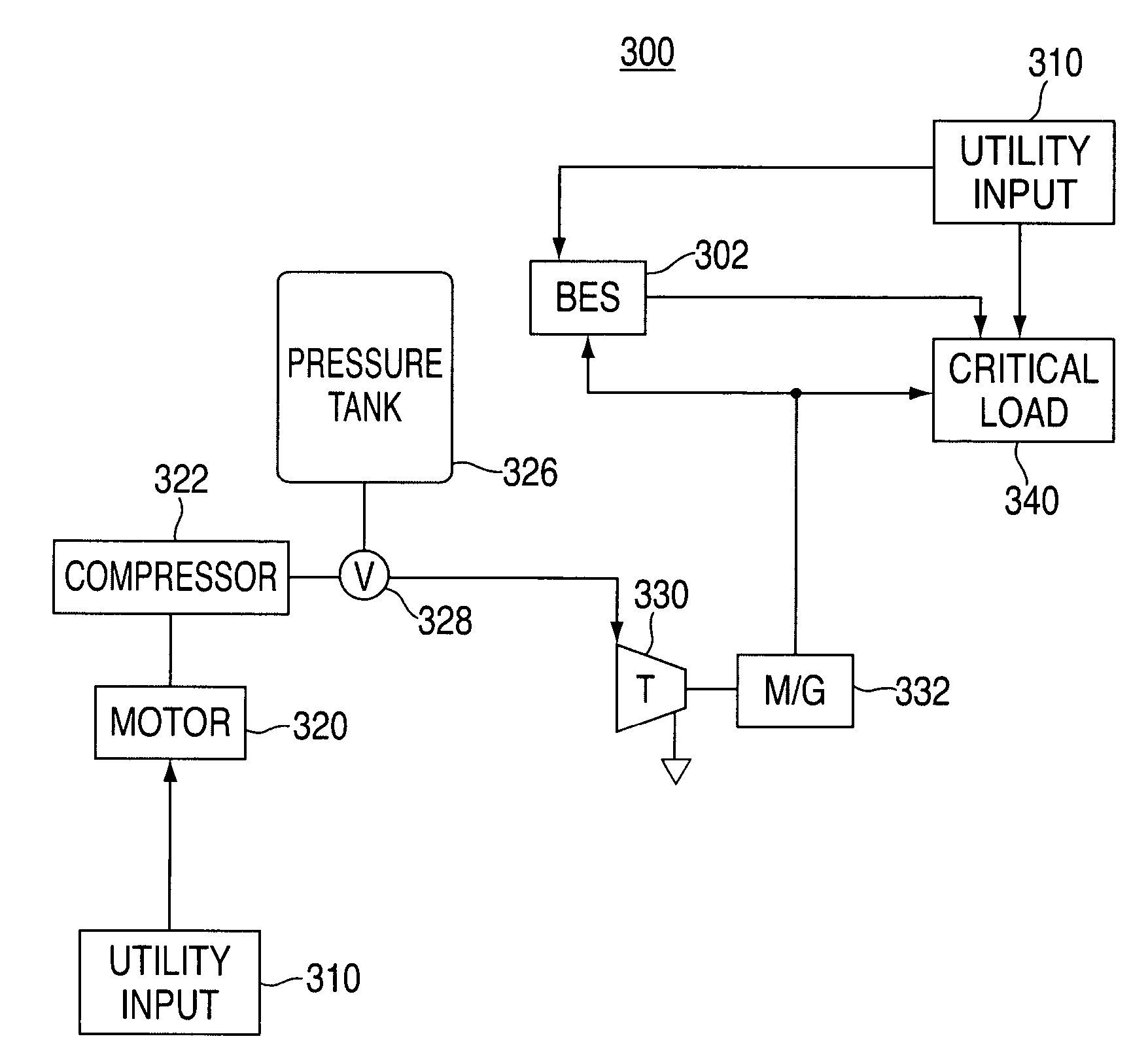
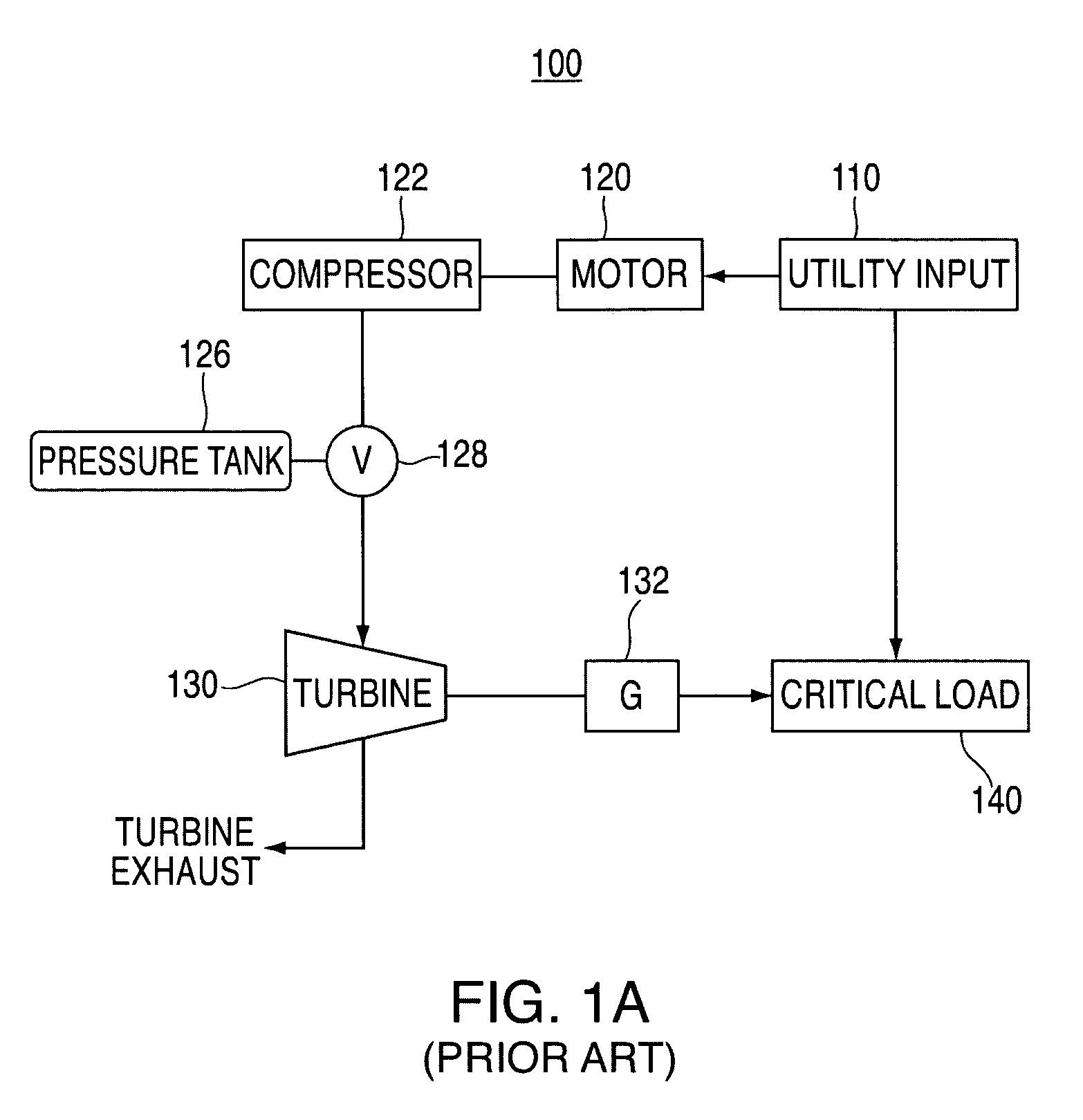
[0038]FIG. 1A shows a conventional CAS system for providing backup power to a load.

[0039]CAS system 100 includes a primary power source, utility input 110, that provides input power to motor 120, which may be any conventional type of motor (e.g., a rotary electric machine). Motor 120 is coupled to compressor 122 such that when motor 120 is receiving input power from utility input 110, it drives compressor 122. Compressor 122, when driven by motor 120, supplies compressed air to pressure tank 126 through valve 128. Compressor 122 may be any type of compressor which compacts or compresses air (e.g., atmospheric air) to occupy a smaller space inside of pressure tank 126.

[0040]As shown in FIG. 1A, pressure tank 126 is coupled to compressor 122 through valve 128. It should be understood, however, that pressure tank 126 in CAS system 100, as well as the pressure tanks associated with the other systems described herein, may be replaced with any other suitable type of air reservoir capable ...


PUM

PropertyMeasurementUnit
timeaaaaaaaaaa
timeaaaaaaaaaa
poweraaaaaaaaaa

Abstract

Backup energy systems utilizing compressed air storage (CAS) systems and bridging energy systems to supply backup power to a load are provided. During a power failure, the bridging energy system provides backup power to the load at least until the CAS system begins supplying adequate power. In various embodiments, backup power capability is enhanced through the use of one or more exhaustless heaters, which are used to heat compressed air. The compressed air, in turn, drives a turbine which is used to power an electrical generator. In various embodiments, ambient air heat exchangers or other types of heat exchangers are used to heat compressed air prior to the compressed air being routed to the turbine, thereby increasing system efficiency. Backup power and backup HVAC are also provided by utilizing turbine exhaust, heat exchangers and various resistive heating elements.

Description

BACKGROUND OF THE INVENTION[0001]This invention relates to backup energy systems for supplying backup power to a load. More particularly, this invention relates to backup energy systems that use the combination of a compressed air storage (CAS) system and an energy storage system, or bridging energy system, to provide backup power to a load during a failure of a primary power source.[0002]CAS systems are well known. CAS systems use compressed air to drive a turbine, which in turn powers an electrical generator. Prior to reaching the turbine, the compressed air may be heated using a suitable type of fuel-combustion system. Alternatively, an exhaustless heater may be used to heat the compressed air. This type of CAS, which uses an exhaustless heater, is known as a combined thermal systems are disclosed in a commonly-assigned, U.S. patent application Ser. No. 10 / 361,729 filed Feb. 5, 2003, entitled “Thermal and Compressed Air Storage System,” now U.S. Pat. No. 7,086,231, which is hereb...

Claims


Application Information

Patent Timeline
Patent Type & Authority Patents(United States)
IPC IPC(8): F01K13/02F02C6/16F24F5/00H02J9/06H02J9/08
CPCF02C6/16F24F5/0085H02J9/08H02J9/062Y02B10/72Y02E60/15Y02B10/70Y02E60/16
Inventor PINKERTON, JOSEPH FBEATTY, DAVIDPERKINS, DAVID E
Owner P10 IND INC
Why Eureka
Try Eureka