Vortex cooling system for a turbine blade

a cooling system and turbine blade technology, applied in the field of hollow turbine blades, can solve the problems of reducing the useful life of the turbine blade, the likelihood of failure, and localized hot spots, and achieve the effects of increasing heat transfer and heat removal, and discharging heat from the turbine blad

Active Publication Date: 2006-10-31
SIEMENS ENERGY INC
View PDF13 Cites 37 Cited by
  • Summary
  • Abstract
  • Description
  • Claims
  • Application Information

AI Technical Summary

Benefits of technology

[0005]This invention relates to a turbine blade capable of being used in turbine engines and having a turbine blade cooling system for dissipating heat from the turbine blade. The cooling system is formed from a plurality of cooling chambers in internal aspects of a turbine blade that extend radially from the platform of the turbine blade and are configured to create vortices of cooling fluids as the cooling fluids flow through the cooling chambers. The rapidly spinning vortices in the cooling chambers increase heat transfer and heat removal relative to conventional designs.
[0009]In one embodiment, one or more of the cooling chambers may include trip strips for increasing turbulence and heat transfer in the cooling chambers. The trip strips increase the internal heat transfer coefficient. The combined cooling effect realized by the combination of the trip strips and the vortex flow yields a high convection cooling efficiency for the turbine blade.
[0010]The cooling chambers may also include purge holes at the blade tip for discharging particles from the turbine blade. The vortices formed in the cooling chambers collect numerous particles along the longitudinal axis of the chambers as a result of the low velocity of cooling fluids found there. Rotation of the turbine blade about an axis creates forces that discharge the particles from the cooling chambers through the purge holes. Thus, the vortex flow of cooling fluids provides enhanced cooling capabilities and functions as a foreign object separator. Use of the purge holes enables the film cooling holes to be sized smaller without an increase in blockages and minimizes formation of blockages in internal bleed slots.
[0011]During operation, cooling fluids are passed through into the cooling cavities from cooling channels in the root of the turbine blade. The cooling fluids enter the leading edge cooling chambers through one or more metering holes and flow in close proximity with the inner surface forming the leading edge cooling chamber, whereby a vortex is formed as the fluids flow from the platform towards the tip around trip strips. This configuration cools the leading edge first, which generally has the highest heat load, before flowing to the mid-chord cooling chambers. As the cooling fluids flow towards the tip, some of the cooling fluids are exhausted through film cooling orifices and some of the cooling fluids flow through bleed slots into the suction side and pressure side mid-chord cooling chambers where the cooling fluids form vortices as well. The flow of cooling fluids into the suction side and pressure side mid-chord cooling chambers is determined based on the heat loads on the pressure and suction sides, which results in a generally uniform airfoil temperature distribution or a generally uniform thermal plane and reduces thermally induced strain.
[0014]An advantage of this invention is that the cooling chambers in the leading edge, the trailing edge, and mid-chord areas of the turbine blade are configured to create vortices of cooling fluids flowing through the cooling chambers. The vortices in these cooling chambers increase the velocity of the cooling fluids flowing in the cooling chambers and therefore, increase the heat transfer in the cooling chambers.
[0015]Another advantage of this invention is that the vortices that form in the cooling chambers cause contaminant particles to collect along the longitudinal axis of the cooling chambers and to be expelled from the turbine blade through purge holes in the tip.

Problems solved by technology

In addition, turbine blades often contain cooling systems for prolonging the life of the blades and reducing the likelihood of failure as a result of excessive temperatures.
However, centrifugal forces and air flow at boundary layers often prevent some areas of the turbine blade from being adequately cooled, which results in the formation of localized hot spots.
Localized hot spots, depending on their location, can reduce the useful life of a turbine blade and can damage a turbine blade to an extent necessitating replacement of the blade.
While many of these conventional systems have operated successfully, the cooling demands of turbine engines produced today have increased and outgrown the cooling capacities of these conventional systems.

Method used


Image

  • Vortex cooling system for a turbine blade
  • Vortex cooling system for a turbine blade
  • Vortex cooling system for a turbine blade

Examples


Embodiment Construction

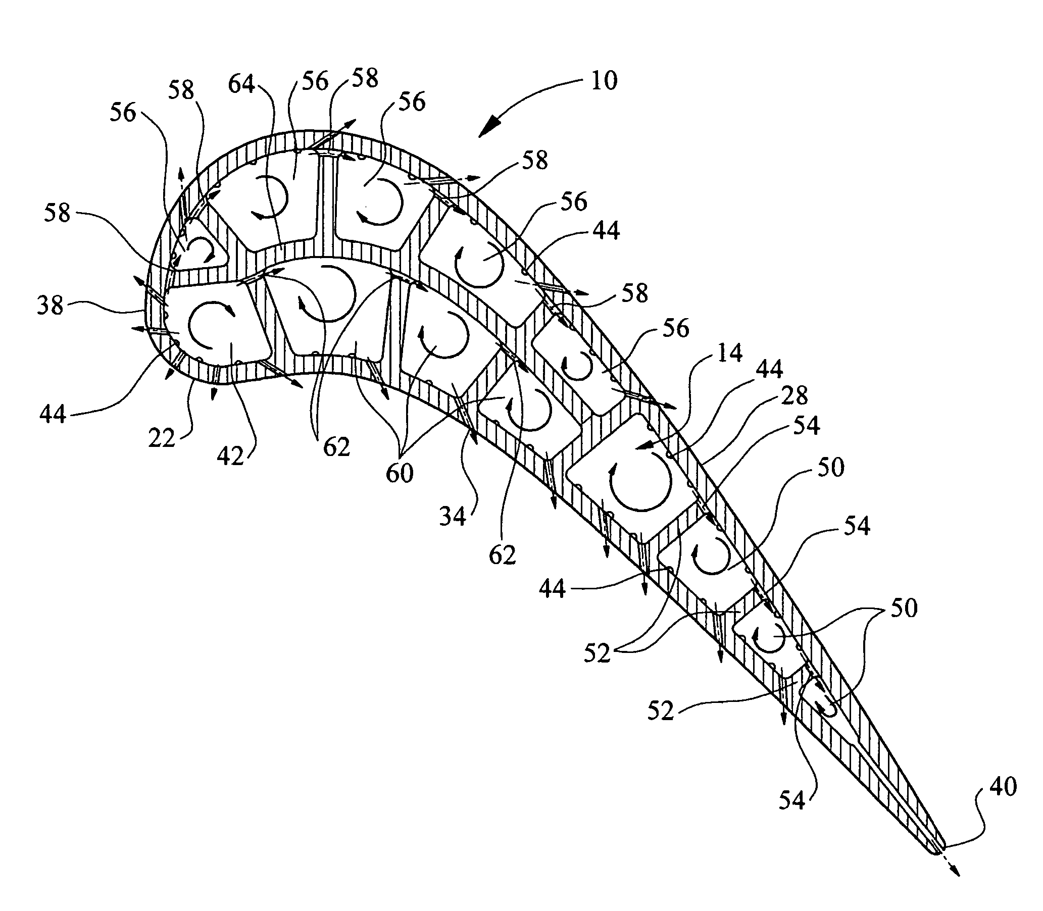
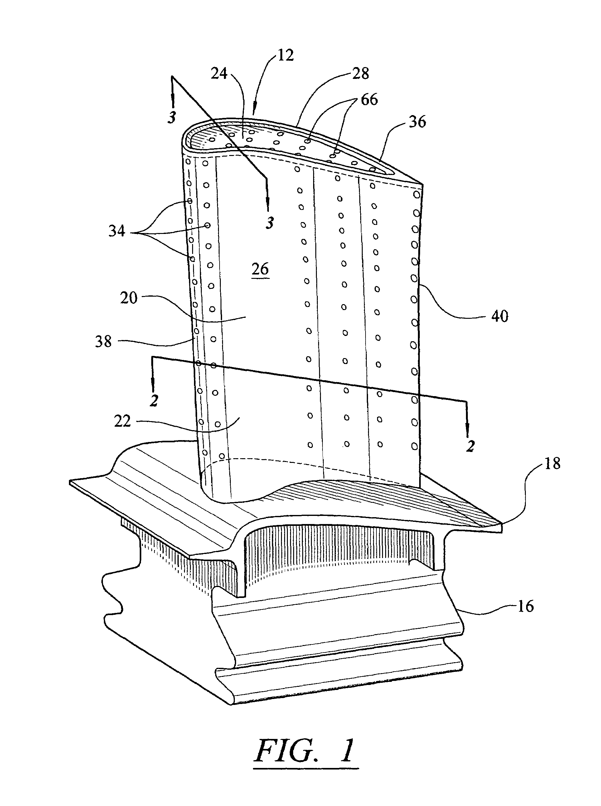
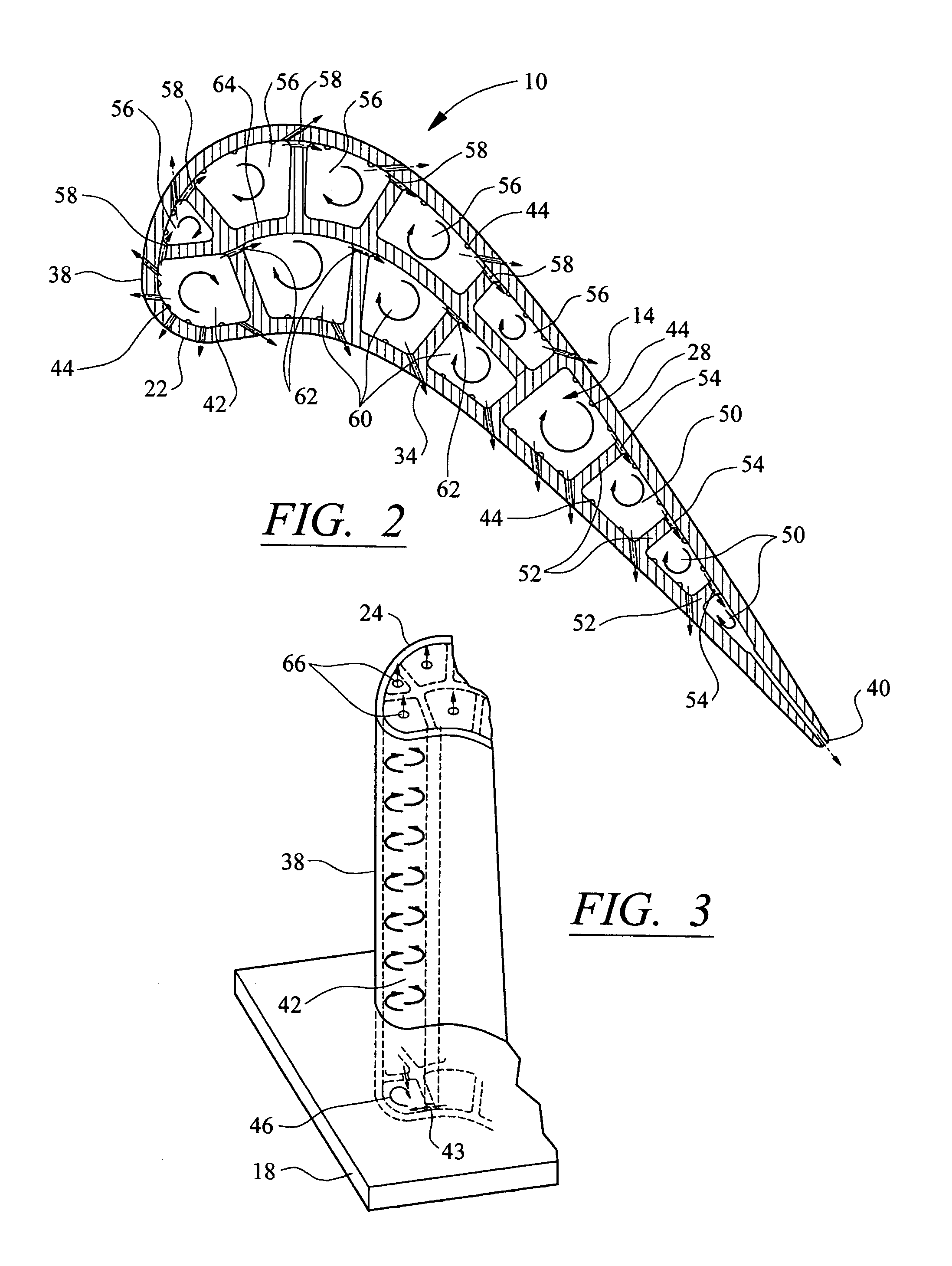
[0021]This invention is directed to a turbine blade cooling system 10 for turbine blades 12 used in turbine engines. In particular, as shown in FIGS. 1–3, the turbine blade cooling system 10 is directed to a vortex cooling system located in a plurality of cooling cavities 14, as shown in FIG. 2, positioned between outer walls 22. The vortex cooling system 10 is composed of a plurality of cavities configured to create vortices of cooling fluids flowing through the cavities for increasing heat transfer between the turbine blade 12 and the cooling fluids flowing through cavities.

[0022]In at least one embodiment, as shown in FIGS. 1–2, the turbine blade 12 may be formed from a root 16 having a platform 18 and formed from a generally elongated blade 20 coupled to the root 16 at the platform 18. The turbine blade may also include a tip 36 generally opposite the root 16 and the platform 18. Blade 20 may have an outer wall 22 adapted for use, for example, in a first stage of an axial flow t...


PUM


Abstract

A turbine blade for a turbine engine having an internal cooling system formed from a plurality of cooling chambers extending radially in the blade and configured to create vortices within the chambers. In at least one embodiment, the cooling system may be formed from leading edge cooling chambers, trailing edge cooling chambers, suction side mid-chord cooling chambers, and pressure side mid-chord cooling chambers that are configured to receive cooling fluids from supply channels in a root of the blade and to create vortices in the cooling chambers. The vortices of cooling fluids increase heat removal from the turbine blade. The cooling fluids may be exhausted from the turbine blade through film cooling orifices.

Description

FIELD OF THE INVENTION[0001]This invention is directed generally to turbine blades, and more particularly to hollow turbine blades having internal cooling channels for passing cooling fluids, such as air, to cool the blades.BACKGROUND[0002]Typically, gas turbine engines include a compressor for compressing air, a combustor for mixing the compressed air with fuel and igniting the mixture, and a turbine blade assembly for producing power. Combustors often operate at high temperatures that may exceed 2,500 degrees Fahrenheit. Typical turbine combustor configurations expose turbine blade assemblies to these high temperatures. As a result, turbine blades must be made of materials capable of withstanding such high temperatures. In addition, turbine blades often contain cooling systems for prolonging the life of the blades and reducing the likelihood of failure as a result of excessive temperatures.[0003]Typically, turbine blades, as shown in FIG. 1, are formed from a root portion and a pl...

Claims


Application Information

Patent Timeline
Patent Type & Authority Patents(United States)
IPC IPC(8): F01D5/18
CPCF01D5/186F05D2260/2212F05D2240/127
Inventor LIANG, GEORGE
Owner SIEMENS ENERGY INC
Why Eureka
Try Eureka