
Cable holder

a cable holder and cable technology, applied in the direction of electrical apparatus, connection, coupling device connection, etc., can solve the problems of difficult soldering and testing of electronic components arranged on the printed circuit board, the difficulty of lamp mounting, etc., to achieve the effect of a particularly simple production of the cable holder

Inactive Publication Date: 2006-10-31
PATENT TREUHAND GESELLSCHAFT FUER ELECTRIC GLUEHLAMPEN M B H
View PDF8 Cites 14 Cited by
  • Summary
  • Abstract
  • Description
  • Claims
  • Application Information

AI Technical Summary

Benefits of technology

The cable holder simplifies the fitting, soldering, and testing of electronic components by maintaining cables in a predetermined relative position, reducing errors and manufacturing complexity, and allowing for efficient integration with printed circuit boards.

Problems solved by technology

Owing to a negative current / voltage characteristic, some lamps, for example, fluorescent lamps, require current limitation devices.
One disadvantage of this is the fact that these connection cables, which have been fixedly soldered in, make manufacture of the electronics, with the fitting, soldering and testing of the electronic components arranged on the printed circuit board, more difficult, since these connection cables take up a considerable amount of physical space and are difficult to manipulate owing to their number and rigidity.
With sequential fitting of the individual connection cables there is also the risk of positions or colors being mixed up, i.e. erroneous fitting of cables such that there are increased requirements for quality control checks.
Another disadvantage of the conventional solutions consists in the fact that this mounting step is comparatively complex since, for this purpose, the individual connection cables need to be inserted into plastic bushings and then the plastic bushings need to be threaded into the cutouts in the EB housing wall in a subsequent manufacturing step.

Method used


Image

  • Cable holder
  • Cable holder
  • Cable holder

Examples


Embodiment Construction

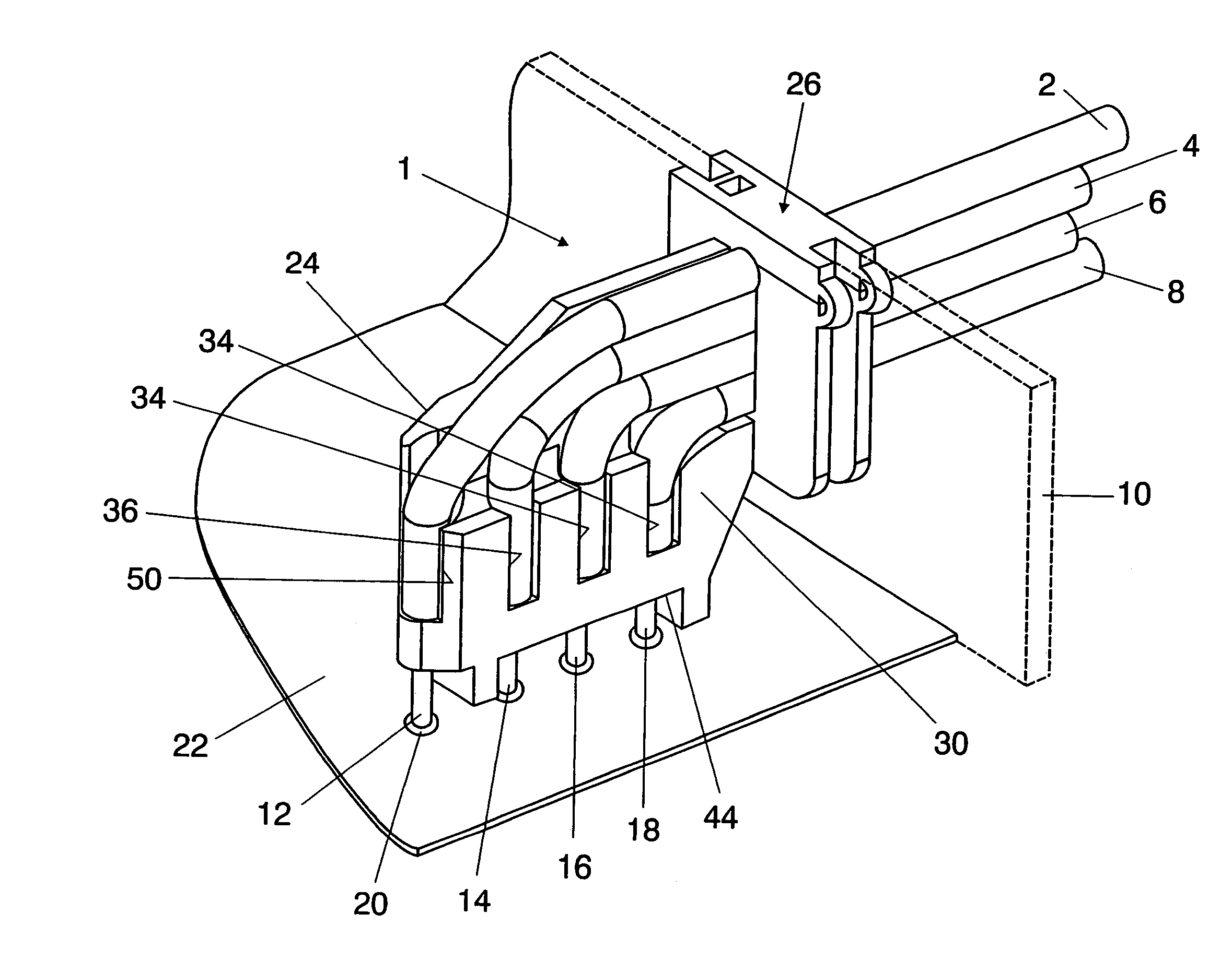
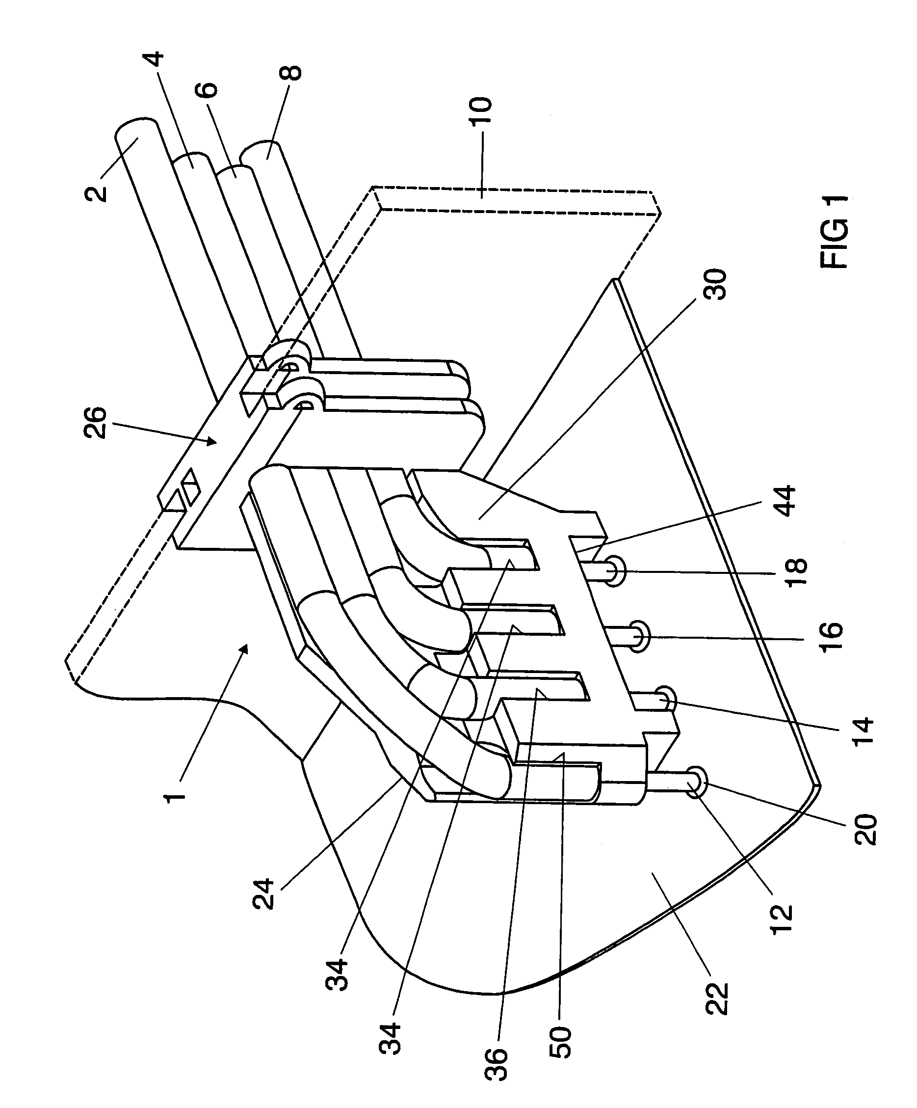
[0020]FIG. 1 shows a three-dimensional illustration of a cable holder 1 for the purpose of fixing four connection cables 2, 4, 6, 8 in position, said connection cables extending through a cutout in a housing wall 10 (indicated by dashed lines) of a housing of an electronic ballast (EB). Cable ends 12, 14, 16, 18, from which the insulation has been stripped, of the connection cables 2, 4, 6, 8 protrude out of the cable holder 1 and are each connected to conductor tracks on a printed circuit board 22 by means of a soldered connection 20. The geometry of the cable holder 1 is designed such that the cable ends 12, 14, 16, 18 are positioned in a predetermined relative position in relation to one another which corresponds to the relative position of the soldered connections 20 in relation to one another, with the result that the cable ends 12, 14, 16, 18 are already aligned in relation to the predetermined soldered points once the cable holder 1 has been inserted into the housing wall 10....


PUM


Abstract

A cable holder 1 for a large number of connection cables 2, 4, 6, 8 of an electrical or electronic control device, in particular of an electronic ballast of a lamp. The cable holder 1 has a base body 24, in which receptacles 32, 34, 36, 50 are formed which surround, at least in sections, an insulating sheath of the connection cables 2, 4, 6, 8 and are associated with apertures 38, 40, 42, 52, which open out into an end face 44 of the base body 24, cable ends 12, 14, 16, 18, from which the insulation has been stripped, of the connection cables 2, 4, 6, 8 extending through the apertures 38, 40, 42, 52.

Description

TECHNICAL FIELD[0001]The invention relates to a cable holder for connection cables of a control device and to an electronic ballast designed to have at least one such cable holder.BACKGROUND ART[0002]Owing to a negative current / voltage characteristic, some lamps, for example, fluorescent lamps, require current limitation devices. Previously, conventional alternating coils which are connected in series with the lamp in conjunction with a starter were used for this purpose. Owing to the high losses in the inductor, these conventional ballasts have been replaced in recent years by electronic ballasts, by means of which the required system performance (the lamp including the ballast) is considerably reduced with respect to the conventional solutions given approximately the same luminous flux of the lamp. For the NAFTA (North American Free Trade Agreement) market, these electronic ballasts (EBs) are predominantly supplied with connection cables which are soldered fixedly to a printed cir...

Claims


Application Information

Patent Timeline
Patent Type & Authority Patents(United States)
IPC IPC(8): H01R12/24H01R12/50H01R12/55
CPCH01R13/5812H01R13/5833
Inventor EBERT, WOLFGANGMAYER, WOLFGANG
Owner PATENT TREUHAND GESELLSCHAFT FUER ELECTRIC GLUEHLAMPEN M B H
Learn More