Percussive massager with variable node spacing

a percussive massager and variable node technology, applied in the field of massage, can solve the problems of irritation or other discomfort of the recipient, difficulty in elastically attaching the connecting rod to the rocker arm, prior art percussive massagers do not offer flexibility or adjustment of the spacing of the massage nodes or formations, etc., to achieve the effect of increasing and decreasing the spacing of the massage nodes and reducing rotation

Inactive Publication Date: 2006-10-31
FKA DISTRIBUTING CO LLC
View PDF52 Cites 22 Cited by
  • Summary
  • Abstract
  • Description
  • Claims
  • Application Information

AI Technical Summary

Benefits of technology

[0009]The percussive massager of the present invention includes a housing supporting a motor having an output shaft. A percussion arm is attached to the motor housing and is operably driven by the motor output shaft. At least one positioning member is movably connected to the percussion arm and at least two massage nodes are operably connected to the percussion arm, one of which is attached to the positioning member. The motor drives the percussion arm wherein the massage nodes are moved toward and away from the massage head portion thereby providing a percussive massage effect. A rotary mechanism, rotatable with respect to the percussion arm, is engaged with the positioning member to drive a portion of the positioning member toward and away from a central region of the massage head portion. An ancillary transmission imparts a reduced rotation from the motor output shaft to the rotary mechanism to progressively increase and decrease the spacing of the massage nodes.

Problems solved by technology

Massagers that exert a percussive effect on the body are preferred over massagers which generate a rubbing action, since the latter type of massager can cause irritation or other discomfort to the recipient.
Additionally, the single input design required the connecting rod to be alternatively loaded in compression and tension making it difficult to elastically attach the connecting rod to the rocker arm.
However, the prior art percussive massagers do not offer any flexibility or adjustment of the spacing of the massage nodes or formations without manual adjustment of the spacing.

Method used


Image

  • Percussive massager with variable node spacing
  • Percussive massager with variable node spacing
  • Percussive massager with variable node spacing

Examples


Embodiment Construction

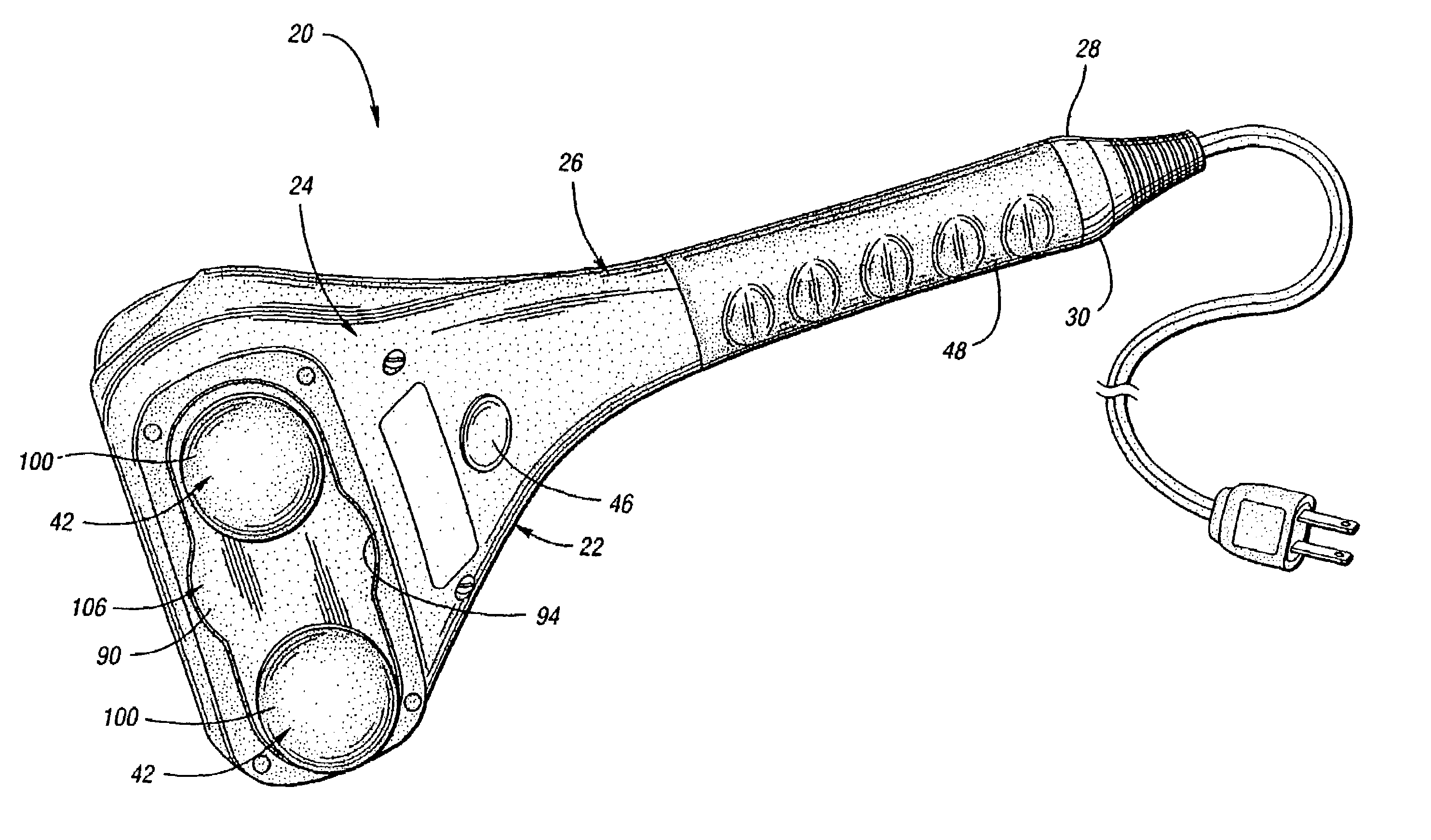
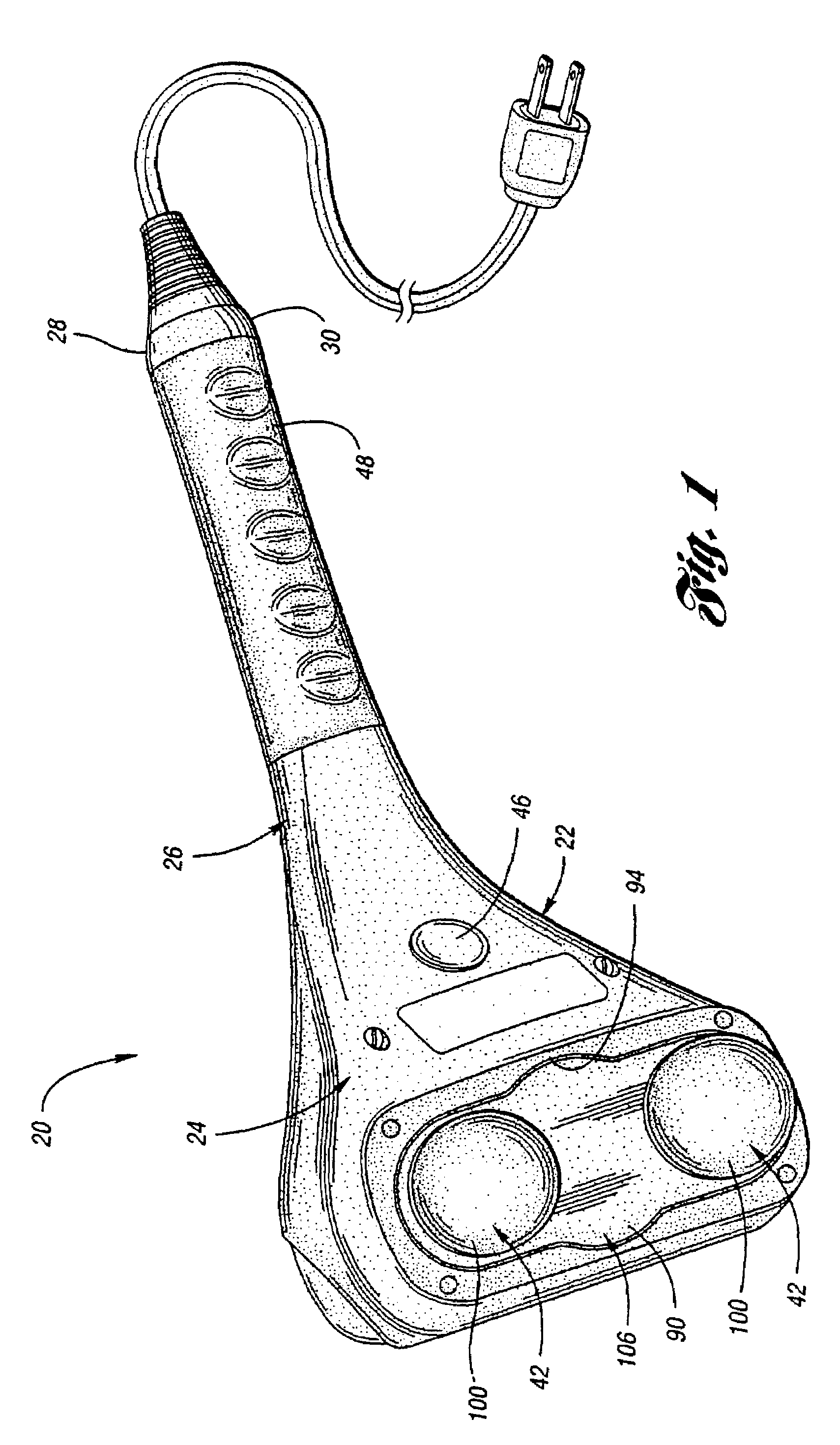
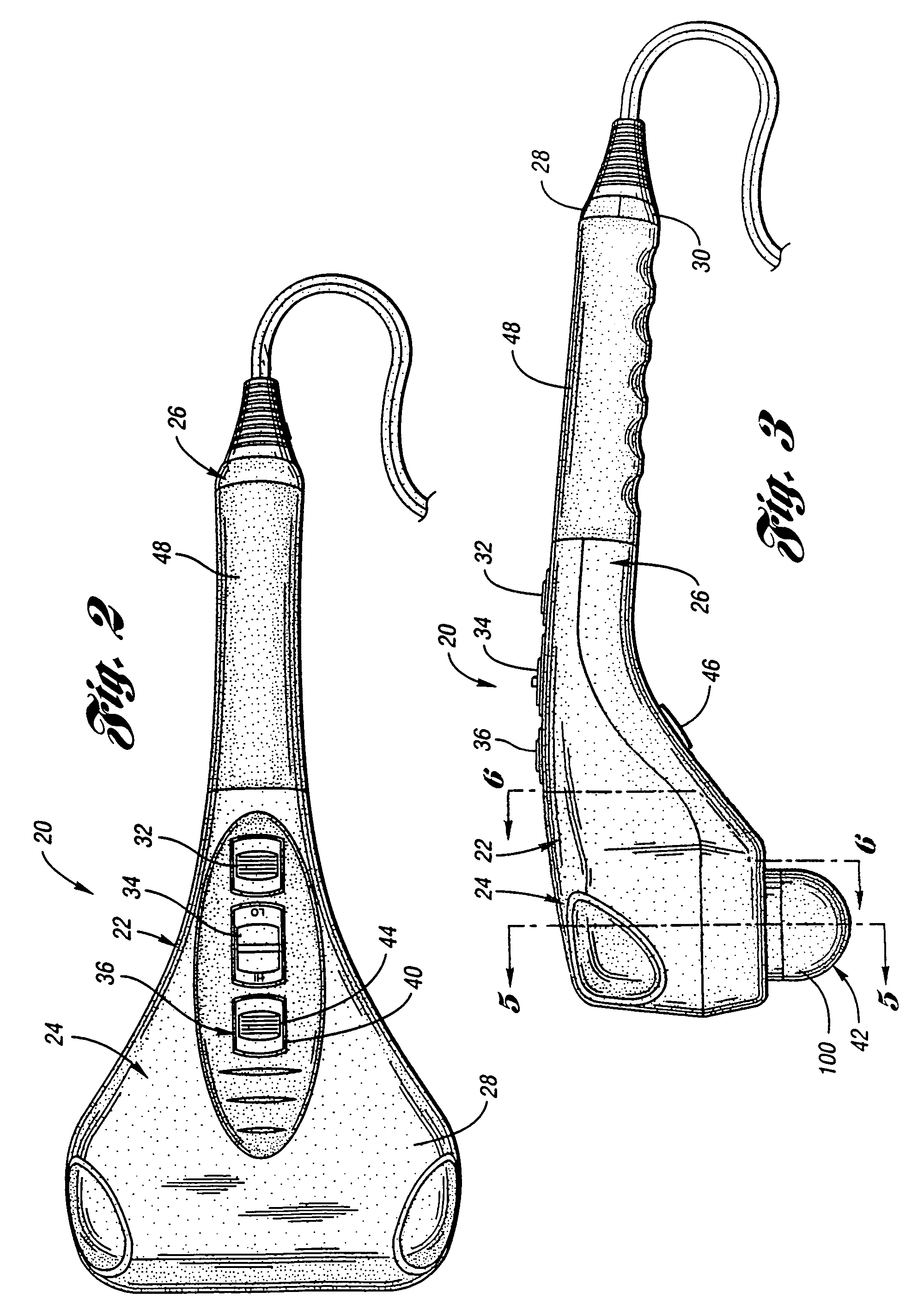
[0027]Referring to FIGS. 1–3, an exemplary and preferred percussive body massager in accordance with the present invention is shown and indicated by reference numeral 20. Massager 20 is a hand held massager and comprises a housing 22 formed generally as two portions, a massage head 24 and a handle 26. Housing 22 is preferably constructed from a plastic material and is assembled from two parts, a top 28 and a bottom 30. Massager 20 is advantageously constructed to be light enough for a user to use it with only one hand if desired.

[0028]As shown in FIGS. 1–3, handle portion 26 is preferably elongate and extends perpendicularly from massage head 24. Handle 26 preferably contains slidable switches for a user's adjustment, as best shown in the top plan view of FIG. 2, which are located on housing top 28 for convenient user access and viewing. The switches include a power switch 32, a variable speed lever 34, and a variable spacing switch 36. The power switch 32 provides three options of ...


PUM


Abstract

A percussive massager is provided having a housing supporting a motor having an output shaft rotatably driven thereby. At least one positioning member is movably connected to a percussion arm which is attached to the housing and operably connected to the motor output shaft. At least two massage nodes are operably connected to the percussion arm, one of which being attached to the positioning member, to form a massage surface and move toward and away from the housing to provide a percussive massage effect. A rotary mechanism is rotatable with respect to the percussion arm and drives the positioning member toward and away from a central region of the housing. An ancillary transmission has an output and an input for operably imparting rotation to the rotary mechanism such that the spacing of the massage nodes progressively increases and decreases.

Description

CROSS-REFERENCE TO RELATED APPLICATIONS[0001]This application claims priority to U.S. application Ser. No. 10 / 108,871, filed Mar. 28, 2002.BACKGROUND OF THE INVENTION[0002]1. Field of the Invention[0003]This invention relates to a massager which exerts a percussive massage effect with nodes having variable spacing.[0004]2. Background Art[0005]Power operated massagers are often used to treat muscle tension and fatigue. Massagers that exert a percussive effect on the body are preferred over massagers which generate a rubbing action, since the latter type of massager can cause irritation or other discomfort to the recipient.[0006]Application Ser. No. 09 / 475,810, filed by same assignee on Dec. 30, 1999, published Oct. 4, 2001 as No. US2001 / 0027280A1 discloses a percussive massager and is incorporated by reference herein. The massager includes a motor having an output shaft extending from either side thereof, the motor being affixed within the housing by a motor support unit. A rocker ar...

Claims


Application Information

Patent Timeline
Patent Type & Authority Patents(United States)
IPC IPC(8): A61H23/02A61HA61H1/00A61H7/00A61H23/00
CPCA61H7/001A61H23/0254A61H23/0263A61H2201/0153A61H2201/0157A61H2201/164A61H2201/1669A61H2205/12
Inventor LEV, MORDECHAIFERBER, ROMAN S.HUANG, CHARLES
Owner FKA DISTRIBUTING CO LLC
Why Eureka
Try Eureka