Optical film

a technology of optical film and film body, applied in the field of optical film, can solve the problems of film cracks and/or variations in retardation, and achieve the effect of excellent contras

Inactive Publication Date: 2006-10-31
NITTO DENKO CORP
View PDF32 Cites 32 Cited by
  • Summary
  • Abstract
  • Description
  • Claims
  • Application Information

AI Technical Summary

Benefits of technology

[0003]Although such an optically biaxial film produces an effect that it provides a liquid crystal display achieving excellent contrast over a wide viewing angle when used in the liquid crystal display, there has been a problem in that it causes iridescence. Also, some optically biaxial films formed of particular polymers have a problem in that cracks and / or variation in retardation may occur in the films.
[0004]Therefore, it is an object of the present invention to provide an optical film having an optical biaxiality, capable of preventing the occurrence of iridescence, the occurrence of cracks, variation in retardation, a poor appearance, and the like when used in various displays such as a liquid crystal display, and further enhancing the display characteristics of the displays.

Problems solved by technology

Although such an optically biaxial film produces an effect that it provides a liquid crystal display achieving excellent contrast over a wide viewing angle when used in the liquid crystal display, there has been a problem in that it causes iridescence.
Also, some optically biaxial films formed of particular polymers have a problem in that cracks and / or variation in retardation may occur in the films.

Method used


Image

  • Optical film
  • Optical film
  • Optical film

Examples


example 1

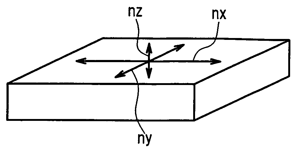
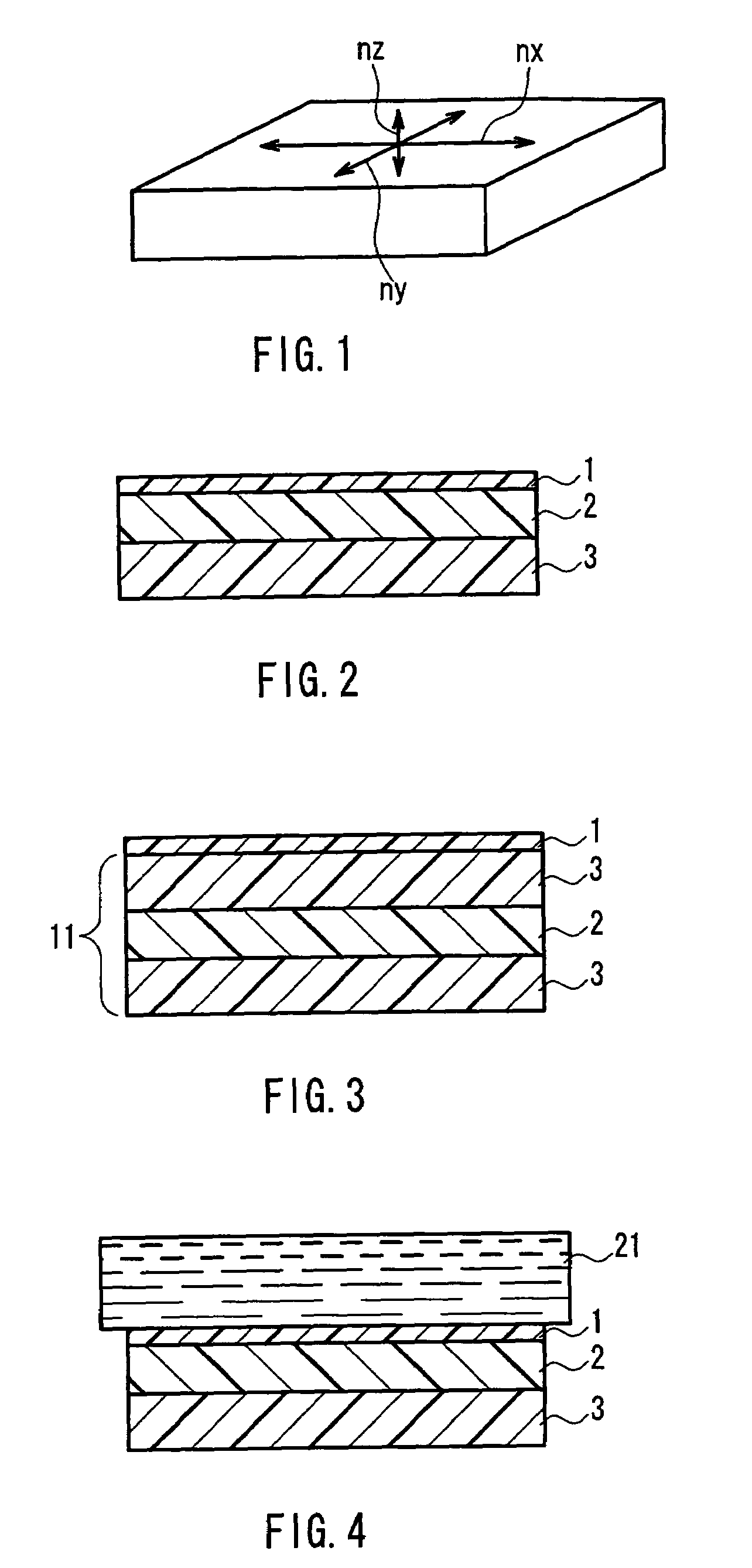
[0155]Polyimide having a weight-average molecular weight (Mw) of 110,000 was first synthesized from 2,2′-bis(3,4-dicarboxyphenyl)hexafluoropropane (6FDA) and 2,2′-bis(trifluoromethyl)-4,4′-diaminobiphenyl (PFMBTFMB) and then dissolved in cyclohexanone to prepare a 15 wt % solution of this polyimide. The thus-obtained polyimide solution was applied onto a 75 μm thick triacetylcellulose (TAC) film (transparent polymer film) prepared by stretching a TAC film to 1.3 times its original length at 175° C. by fixed-end transverse stretching. Thereafter, the film having a layer of the polyimide solution was heat-treated at 100° C. for 10 minutes, thus forming a completely transparent and smooth birefringent layer (a) (polyimide film) having a thickness of 6 μm on the TAC film. In this manner, an optical film was obtained. The birefringent layer (a) of this optical film exhibited optical characteristics satisfying nx>ny>nz.

example 2

[0156]Polyaryletherketone A (trade name) (manufactured by Nippon Shokubai Co., Ltd.) represented by the above formula (18) and having a molecular weight of 200,000 was dissolved in methyl isobutyl ketone to prepare a 20 wt % solution of the Polyaryletherketone A. The thus-obtained polyaryletherketone solution was applied onto a 75 μm thick triacetylcellulose (TAC) film (transparent polymer film) prepared by stretching a TAC film to 1.3 times its original length at 175° C. by fixed-end transverse stretching. Thereafter, the film having a layer of the polyaryletherketone solution was heat-treated at 100° C. for 10 minutes, thus forming a completely transparent and smooth birefringent layer (a) having a thickness of 10 μm on the TAC film. In this manner, an optical film was obtained. The birefringent layer (a) of this optical film exhibited optical characteristics satisfying nx>ny>nz.

example 3

[0157]The same polyimide solution as in Example 1 was applied onto a TAC film (transparent polymer film). Thereafter, the film having a layer of the polyimide solution was heat-treated at 100° C. for 10 minutes, thus forming a completely transparent and smooth birefringent layer (a) having a thickness of 4.2 μm on the TAC film. The thus-obtained laminate of the birefringent layer (a) and the TAC film was stretched 10% at 150° C. by uniaxial-longitudinal stretching. In this manner, an optical film was obtained. The optical film has a thickness of 4 μm and the birefringent layer (a) of this optical film exhibited optical characteristics satisfying nx>ny>nz.


PUM

PropertyMeasurementUnit
thicknessaaaaaaaaaa
thicknessaaaaaaaaaa
thicknessaaaaaaaaaa

Abstract

An optical film including a transparent polymer film (b) and a birefringent layer (a) formed of a polymer and laminated above the transparent polymer film (b) is provided. The birefringent layer (a) and the transparent polymer film (b) satisfy the following formula (1), the birefringent layer (a) satisfies the following formulae (2) and (3), and the polymer forming the birefringent layer (a) has a weight-average molecular weight in the range between 10,000 and 400,000 inclusive.Δn(a)>Δn(b)×10  (1)1<(nx−nz) / (nx−ny)  (2)0.0005≦Δn(a)≦0.5  (3)This optical film can prevent the occurrence of iridescence, the occurrence of cracks, and the occurrence of variation in retardation.

Description

TECHNICAL FIELD[0001]The present invention relates to an optical film suitable for optical compensation of a liquid crystal cell.BACKGROUND ART[0002]Conventionally, a retardation plate has been used in various liquid crystal displays in order to achieve optical compensation. As such a retardation plate, an optically uniaxial film or an optically biaxial film has been used, for example. The optically uniaxial film can be produced, for example, by forming a particular polyimide into a film. The optical uniaxiality of the film is derived from the nature of the polyimide itself, and the obtained film exhibits negative uniaxial optical characteristics (see H8(1996)-511812 A, for example). On the other hand, the optically biaxial film has an excellent optical compensation function. For example, when the optically biaxial film is arranged as an optical film between a liquid crystal cell and a polarizer of a liquid crystal display, it can enhance the display characteristics of the liquid cr...

Claims


Application Information

Patent Timeline
Patent Type & Authority Patents(United States)
IPC IPC(8): C09K19/00B32B27/08G02B5/30
CPCB32B27/08G02B5/3083Y10T428/10Y10T428/1036C09K2323/00C09K2323/03G02B5/30G02F1/1335G02F1/13363B32B27/306B32B2307/42B32B2457/202B32B2551/00
Inventor MURAKAMI, NAONISHIKOUJI, YUUICHIHAYASHI, MASAKIYOSHIMI, HIROYUKI
Owner NITTO DENKO CORP
Why Eureka
Try Eureka