
Flashing light control apparatus and method thereof

a flashing light and control apparatus technology, applied in the field of flashing light control apparatus, can solve the problems of reducing the working efficiency of the cpu, increasing the cost and increasing the power consumption of electrical products, so as to achieve the effect of increasing the power consumption and volume of electrical products

Active Publication Date: 2006-10-31
HTC CORP
View PDF8 Cites 31 Cited by
  • Summary
  • Abstract
  • Description
  • Claims
  • Application Information

AI Technical Summary

Benefits of technology

[0007]Therefore, the main purpose of the present invention is to provide a flashing light control method and apparatus thereof to make many lights flash but not increase the power consumption and volume of a electrical product.
[0009]A further purpose of the present invention is to provide a flashing light control method and apparatus thereof to control the flashing light period without reducing CPU efficiency.

Problems solved by technology

However, the CPU has to keep working in this method, which increase the power consumption of the electrical products.
Additionally, the working efficiency of the CPU is reduced because the partial calculation period is used to generate the pulse signals.
However, an additional oscillation circuit is required in this method, which increase the cost and the volume of the electrical products.
Moreover, the oscillation circuit can only generate a pulse signal with a fixed period.
Therefore, the flashing period is also fixed, which limits the application range thereof.
However, although this method can resolve the fixed period problem, a pulse signal generator can only provide a pulse signal.
If the number of pulse signal generators built in a CPU is not enough, an additional pulse signal generator must be attached to the CPU, which increase the manufacturing cost and the volume of a electrical product.

Method used


Image

  • Flashing light control apparatus and method thereof
  • Flashing light control apparatus and method thereof
  • Flashing light control apparatus and method thereof

Examples


Embodiment Construction

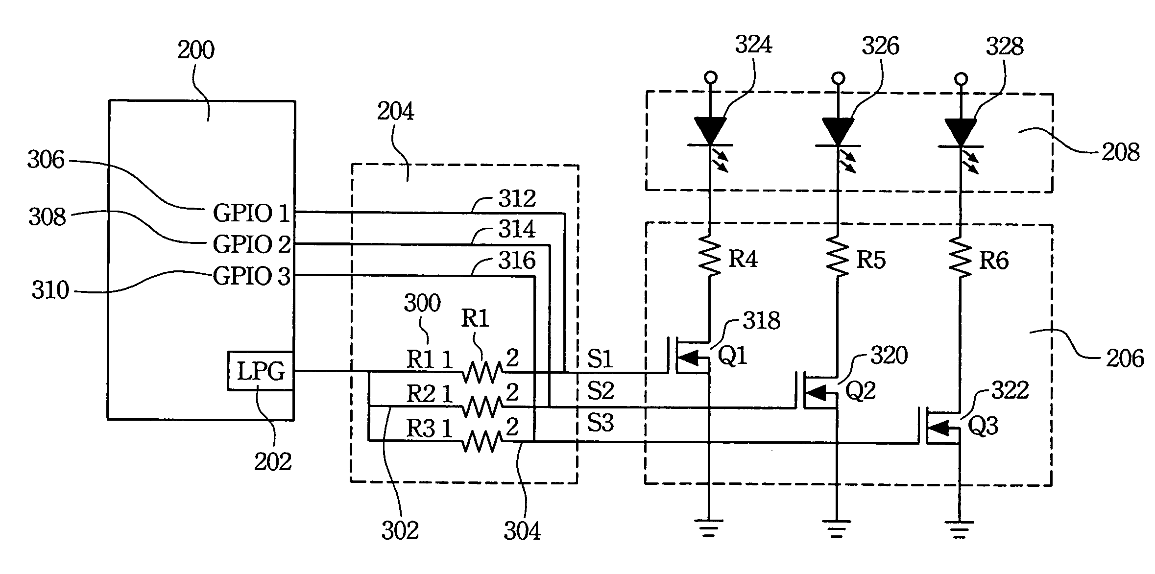
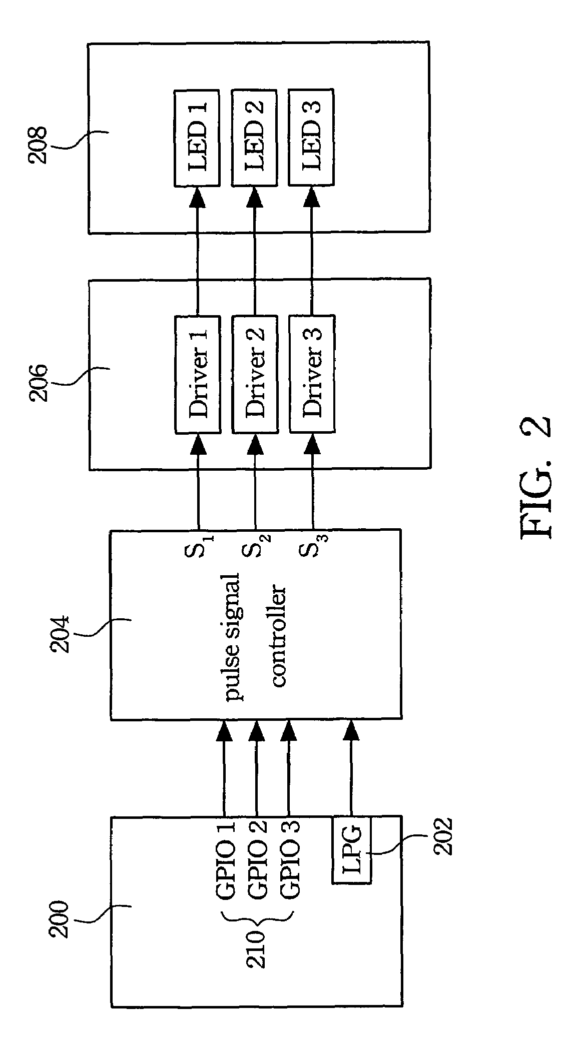
[0018]FIG. 2 is a block diagram of a control circuit according to the first embodiment. According to the first embodiment, a CPU 200 with a low pulse generator (LPG) 202 makes lights flash by controling the states of the general purpose Input / Output (GPIO) pins 210 and thereby selecting which light flahses. The pulse signal generated by the low pulse generator 202 makes the selected light flash. A pulse signal controller 204 triggers a specific driving circuit in the driving circuitdriving circuit module 206 according to the states of the general purpose Input / Output (GPIO) pins 210 of the CPU 200. Then, the pulse signal received by the pulse signal controller 204 can make a specific light in the light module 208 flash through the triggered driving circuit. The light module is composed of light emitting diodes respectively connected to corresponding driving circuits.

[0019]FIG. 3 is a control circuit diagram according to the block diagram illustrated in the FIG. 2. Reference is made ...


PUM


Abstract

The present invention describes a flashing light apparatus and method for operating the same. A pulse signal generated by a pulse signal generator and the states of the general purpose Input / Output pins of a CPU are used to control the lights to flash.

Description

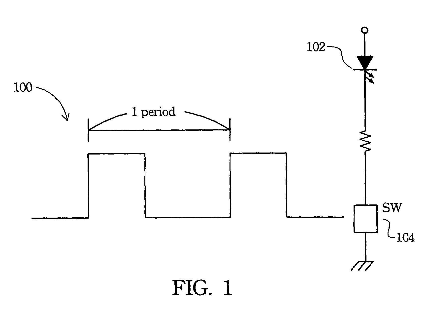
RELATED APPLICATIONS[0001]The present application is based on, and claims priority from, Taiwan Application Ser. No. 93123966, filed on Aug. 10, 2004, the disclosure of which is hereby incorporated by reference herein in its entirety.FIELD OF THE INVENTION[0002]The present invention relates to a light control method, specifically relates to a flashing light control method and apparatus thereof.BACKGROUND OF THE INVENTION[0003]In electrical products, it is necessary to use different flashing lights to represent different operation situations. In FIG. 1, a low pulse signal 100 controls a switching device 104 that makes a light emitting diode 102 flash.[0004]Typically, there are two methods of generating the low pulse signal 100. One is to use a program to control a counter in a CPU to output the pulse signals from the general purpose input / output pins. The pulse signals make the switching devices switch the light emitting diodes on / off. However, the CPU has to keep working in this met...

Claims


Application Information

Patent Timeline
Patent Type & Authority Patents(United States)
IPC IPC(8): H05B39/00G08B5/22
CPCH05B33/0803H05B33/0827H05B33/0842H05B45/32H05B45/46
Inventor TSAI, JUNG-YUANCHEN, KUO-FENGCHIEN, CHUNG-ANCHEN, WEI-SHAO
Owner HTC CORP
Learn More