Digital to analog converter

a digital to analog converter and converter technology, applied in the field of digital to analog converters, can solve the problems of poor linearity of the r-2r network digital to analog converter, signal distortion or loss is expected to be very severe, resistor resistance is expected to be very high, and achieves the effect of high quality performan

Inactive Publication Date: 2006-10-31
BEYOND INNOVATION TECH
View PDF10 Cites 9 Cited by
  • Summary
  • Abstract
  • Description
  • Claims
  • Application Information

AI Technical Summary

Benefits of technology

[0016]A main object of the present invention is to provide a digital to analog converter which is adapted to optimally convert a digital signal into an analog signal for use by analog-type LCDs, without using any unity gain buffer to accompany high quality performance of the digital to analog converter.
[0018]Another object of the present invention is to provide a digital to analog converter which is capable of minimizing accurate and effective transformation from a digital signal to an analog signal so as to resolves the difficulties subsisted in conventional arts.

Problems solved by technology

There are disadvantages regarding this conventional R-2R network digital to analog converter which is applied to an analog LCD.
However, the linearity of the R-2R network digital to analog converter becomes poor when the resistances of resistors of the R-2R network 121 are reduced.
In other words, signal distortion or loss is expected to be very severe.
However, a major drawback of employing this unity gain buffer 321 is that a high quality unity gain buffer 321 is usually expensive.
Moreover, the performance of the digital to analog converter is then solely dependent on the performance and characteristics of the unity gain buffer 321 such that the flexibility in introducing any additional features to the R-2R network digital to analog converter is substantially undermined.

Method used


Image

  • Digital to analog converter
  • Digital to analog converter
  • Digital to analog converter

Examples


Embodiment Construction

[0043]In the following detailed description of the present invention, numerous specific details are set forth in order to provide a thorough understanding of the present invention. However, it will be obvious to one skilled in the art that the present invention may be practiced without these specific details. In other instances well known methods, procedures, components, and circuits have not been described in detail so as not to unnecessarily obscure aspects of the present invention.

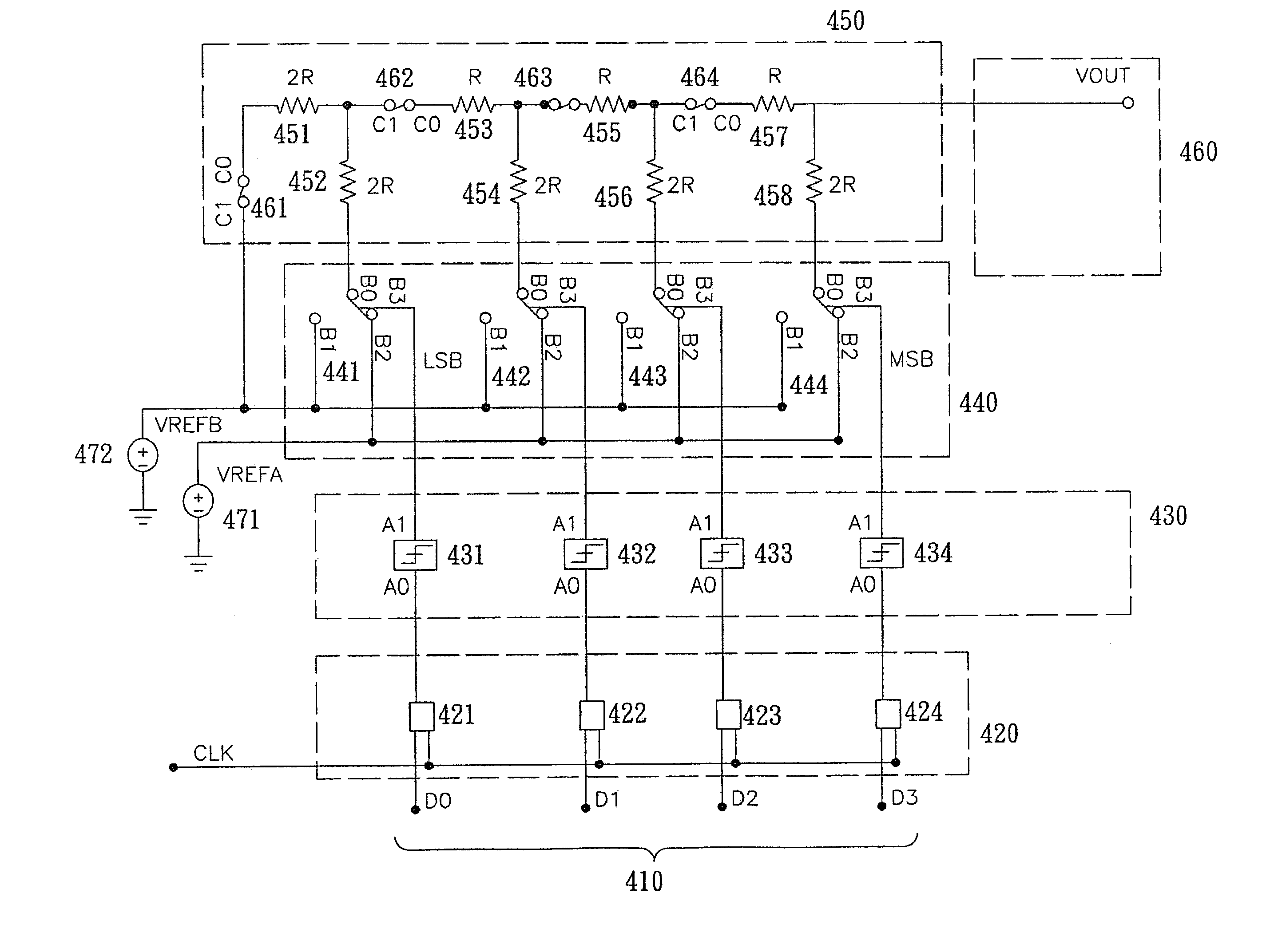
[0044]Referring to FIG. 4 of the drawings, a digital to analog converter according to a preferred embodiment of the present invention is illustrated, in which the digital to analog converter for an analog Liquid Crystal Display (LCD) comprises a digital input 410, a latching circuitry 420, a voltage level shifter circuitry 430, a switching circuitry 440, a resistance network with a resistance compensatory circuitry 450, and a LCD analog output 460. The digital input 410 contains a four digital input ter...


PUM


Abstract

A digital to analog converter for an analog Liquid Crystal Display (LCD) includes a digital inlet, a latching circuitry, a voltage level shifter circuitry, a switching circuitry, and a resistance network with a resistance compensatory circuitry. The resistance network with the resistance compensatory circuitry is electrically connecting with the switching circuitry and adapted to regulate a pattern of the analog output signal so as to optimize the analog output signal. Specifically, the resistance network with a resistance compensatory circuitry is to produce the best linear conversion from the digital signal to the analog signal for use by the LCD.

Description

BACKGROUND OF THE PRESENT INVENTION[0001]1. Field of Invention[0002]The present invention relates to a digital to analog converter, and more particularly to a digital to analog converter with resistance network with a resistance compensatory circuitry which is adapted to optimally convert a digital signal into an analog signal for use by analog-type LCDs.[0003]2. Description of Related Arts[0004]Liquid Crystal Displays (LCD) have been widely accepted as a major alternative to traditional Cathode-Ray Tube (CRT) display. They have the advantages of being smaller in size, clearer in displaying images, and substantially reducing radiation. There exist two major types of LCD, namely, analog and digital LCDs. The distinction implies that the LCD in question may only accept respectively, analog or digital signals for displaying a particular image on the screen. In order to process digital signals in an analog LCD, or vice versa, it definitely requires a converter which is capable of conver...

Claims


Application Information

Patent Timeline
Patent Type & Authority Patents(United States)
IPC IPC(8): H03M1/66
CPCH03M1/0612H03M1/785
Inventor SHIU, SHIAN SUNGLEE, LI-MINYU, CHUNG-CHE
Owner BEYOND INNOVATION TECH
Why Eureka
Try Eureka