
Method and system for video display with automatic reframing

a technology of automatic reframing and video, applied in the field of image processing, can solve the problems of insufficient accuracy of known methods, limited flexibility of known methods, and inability to detect black lines

Active Publication Date: 2006-10-31
STMICROELECTRONICS SRL
View PDF25 Cites 16 Cited by
  • Summary
  • Abstract
  • Description
  • Claims
  • Application Information

AI Technical Summary

Benefits of technology

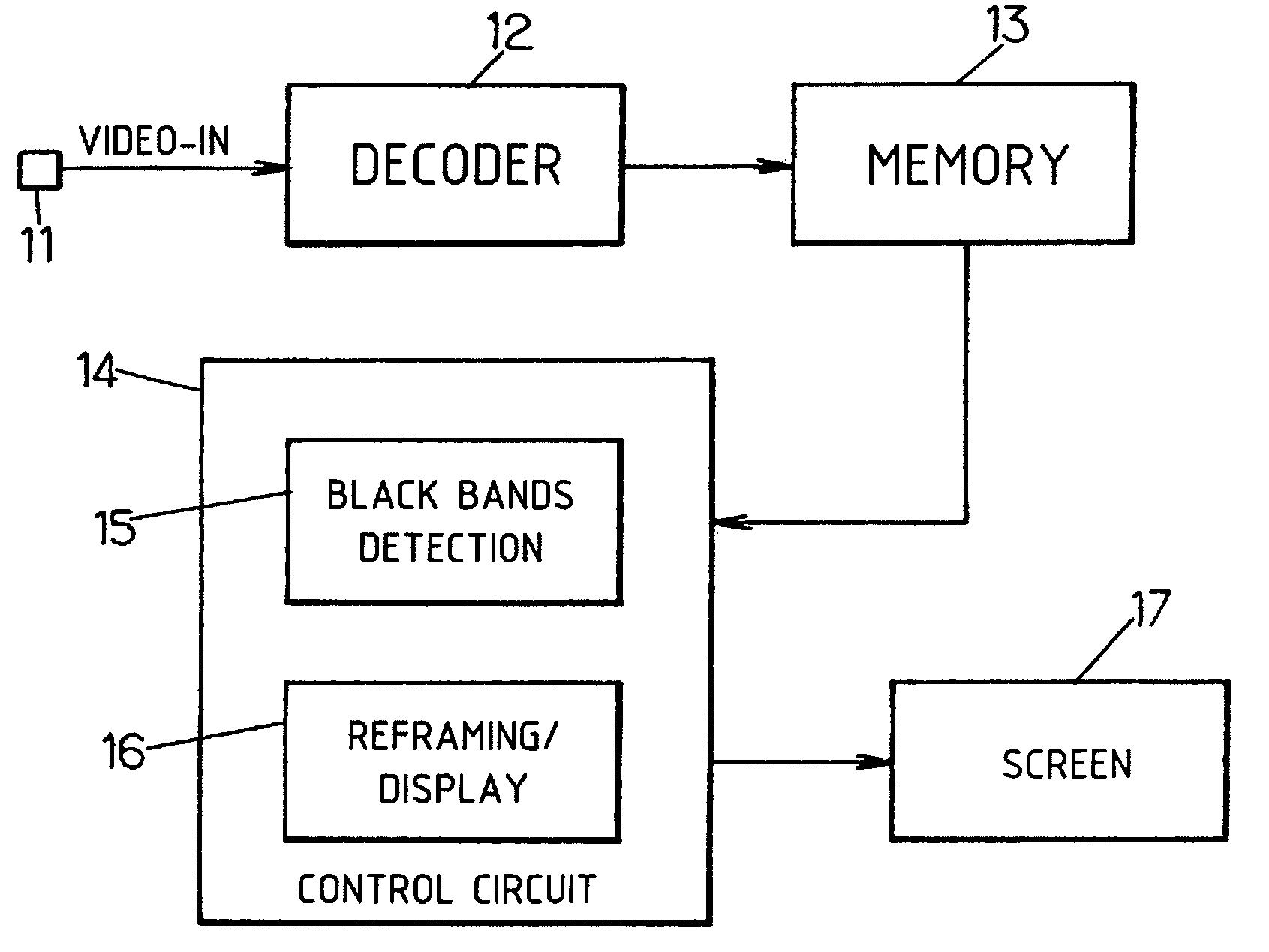
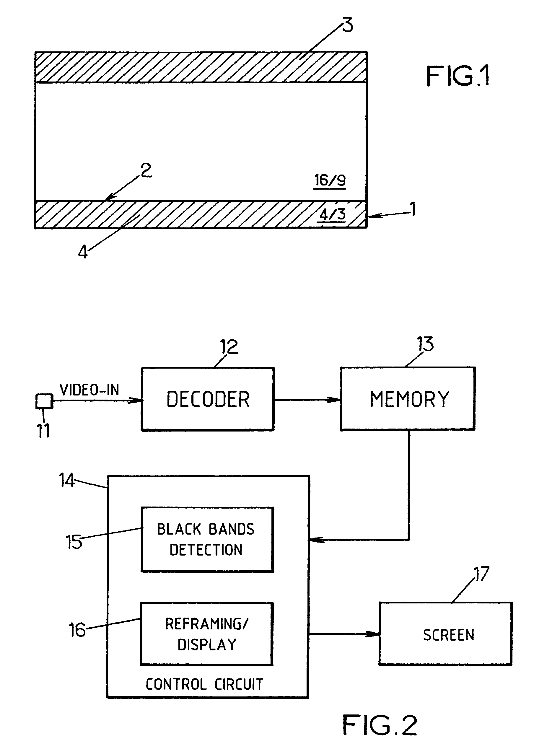
[0016]Advantageously, the sub-sampling of the image which results from the consideration of only the reference pixels gives better results for the detection of the black bands. Another advantage of the present invention is that it can be implemented in software form, so that changes are possible at less cost. Furthermore, the fact that only some of the pixels of the image are processed (namely, the reference pixels) decreases the number of calculations and the resources required.
[0017]Other objects, features and advantages of the present invention will become apparent from the following detailed description. It should be understood, however, that the detailed description and specific examples, while indicating preferred embodiments of the present invention, are given by way of illustration only and various modifications may naturally be performed without deviating from the present invention.

Problems solved by technology

These known methods nevertheless exhibit insufficient accuracy, in the sense that the detection of the black lines may be deficient in a certain number of situations, depending on the content of the images.
Moreover, the known methods exhibit limitations in terms of flexibility (e.g., no possibility of changes) as well as a higher cost when they are implemented in hardware.

Method used


Image

  • Method and system for video display with automatic reframing
  • Method and system for video display with automatic reframing
  • Method and system for video display with automatic reframing

Examples


Embodiment Construction

[0024]Preferred embodiments of the present invention will be described in detail hereinbelow with reference to the attached drawings.

[0025]In the following description, the term “image” is used generically to designate either a video image or a video frame. Moreover, in accordance with the jargon of a person of ordinary skill in the art, “active video” designates the portion of an image which carries the action, that is to say which goes from the first to the last video line which are not black lines.

[0026]The words such as “first”, “last”, and “next”, when they pertain to lines of the image, are here conventionally used with reference to the order of transmission of the information coding the video lines, according to which of the video lines of each image are transmitted in succession commencing with the top line and finishing with the bottom line of the image. It will be noted that this convention is not affected by the fact that the video lines are generally transmitted with int...


PUM


Abstract

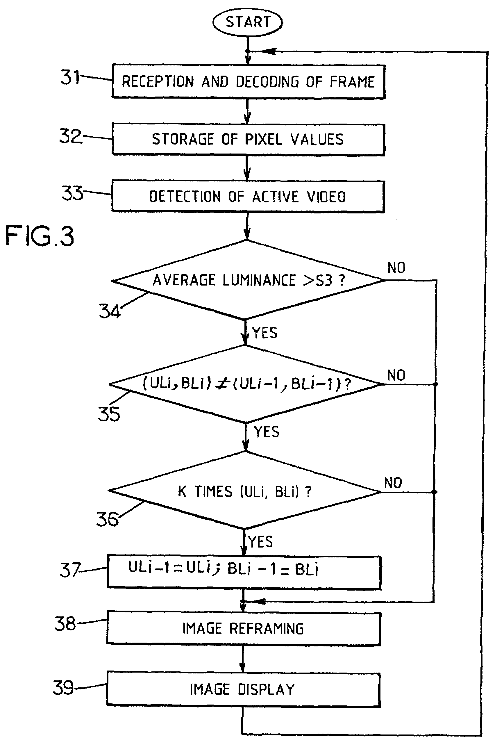
A system and method are provided for displaying a video composed of images each comprising a predetermined number M of lines and, a predetermined number N of pixels in each line. Values of a predetermined number P of reference pixels for each line of a current image of the video are stored in memory, where P is less than N. For each line of the current image, the value of a parameter associated with the line is determined, with the parameter corresponding to the number of the reference pixels of the line that are black according to a first predetermined criterion. A first nonblack line and a last nonblack line of the current image are determined to serve as a basis for an automatic reframing of the images of the video before display. The first nonblack line of the current image is determined by excluding, starting from a first line of the image, the lines of the image which are black according to a second predetermined criterion based on the parameter, and the last nonblack line of the current image is determined by excluding, starting from a last line of the image, the lines of the image which are black according to the second predetermined criterion based on the parameter.

Description

CROSS-REFERENCE TO RELATED APPLICATIONS[0001]This application is based upon and claims priority from French Patent Application No. 02-12233, filed Oct. 3, 2002, the entire disclosure of which is herein incorporated by reference.BACKGROUND OF THE INVENTION[0002]1. Field of the Invention[0003]The present invention relates to image processing, and more specifically to systems and methods for displaying with automatic reframing a video on a display screen such as a television screen.[0004]2. Description of Related Art[0005]The available display screens exhibit a predetermined screen ratio (also referred to as the video format or aspect ratio or aspect format), that is to say the width / height ratio of an image. For example, standard televisions have a screen ratio of 1.33:1 (4 / 3 or standardized format), that is to say they are 1.33 times as wide as they are high. Likewise, widescreen televisions have a screen ratio of 1.78:1 (16 / 9 or widescreen format). Certain televisions may effect the...

Claims


Application Information

Patent Timeline
Patent Type & Authority Patents(United States)
IPC IPC(8): H04N7/01H04N5/46H04N5/44H04N5/445
CPCH04N7/0122H04N21/4884Y10S348/913
Inventor BARNICHON, CHRISTOPHE
Owner STMICROELECTRONICS SRL
Learn More