
Resin intake manifold for multicylinder engine

a multi-cylinder engine and intake manifold technology, applied in the direction of air intakes for fuel, combustion-air/fuel-air treatment, machines/engines, etc., can solve the problems of mass productivity, difficulty in maintaining a satisfactory welding strength, etc., to improve the rigidity of the throttle body mounting part, increase rigidity, and firm intake manifold

Inactive Publication Date: 2006-11-07
DAIKYONISHIKAWA CORP
View PDF8 Cites 10 Cited by
  • Summary
  • Abstract
  • Description
  • Claims
  • Application Information

AI Technical Summary

Benefits of technology

[0010]The present invention has been achieved in view of the above-described problems. An object of the present invention is to provide a firm intake manifold by giving a twist to the way of separating the intake manifold into parts and the configuration of the separated manifold components so that the manifold components are welded at high strength.
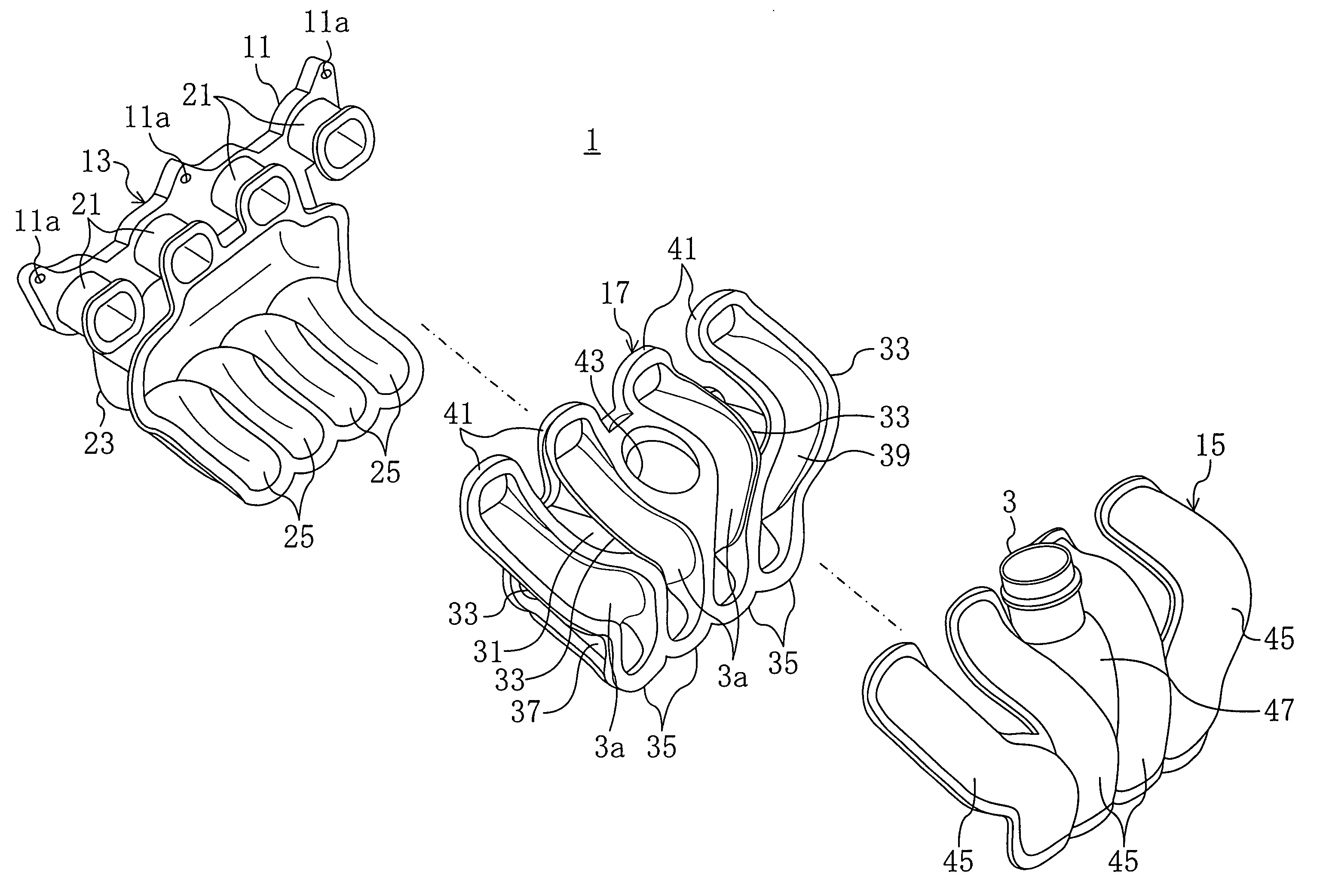
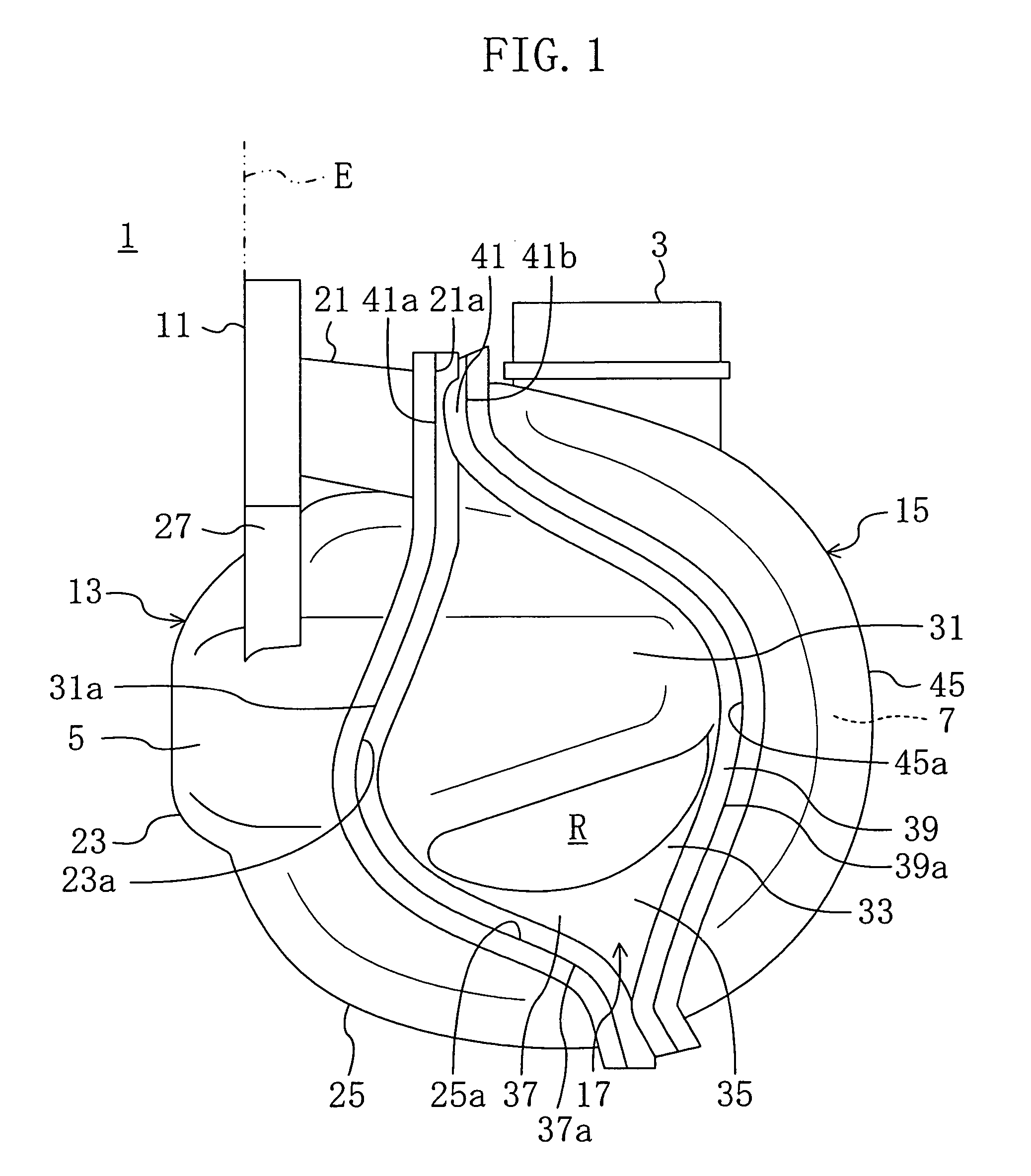
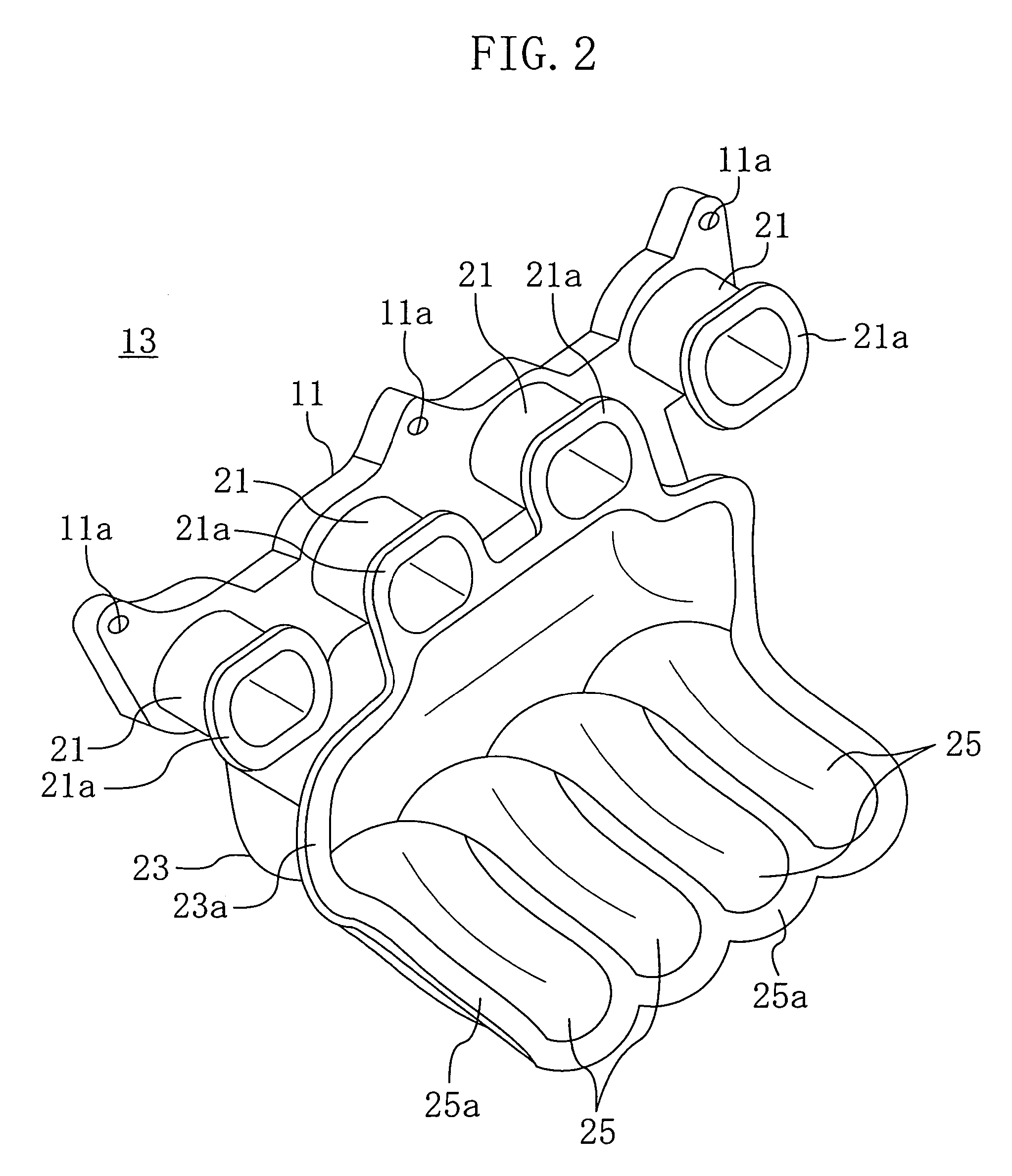
[0013]Where the intake manifold is mounted on the engine, the second path-forming parts of the middle manifold component are jointed on the first path-forming parts of the near manifold component. Therefore, the weight of the middle manifold component is applied to press the second path-forming parts against the first path-forming parts, i.e., it is not applied in such a direction that the first and second path-forming parts separate from each other. Thus, the welding strength between the first and middle manifold components is ensured. Further, since the third path-forming parts of the middle manifold component and the fourth path-forming parts of the far manifold component constitute vertically curved portions of the intake paths, the welding interface between the third and fourth path-forming parts also extends in the vertical direction in a curve. Therefore, the weight of the far manifold component is applied to shear the welding interface. As a result, unlike the conventional intake manifold in which the weight of the manifold component is applied to separate the welded manifold components, the intake manifold of the present invention ensures the welding strength. The configuration of the manifold components allows obtaining satisfactory welding strength among the manifold components, thereby making the intake manifold firm.
[0014]Further, according to the present invention, the intake manifold is assembled from three separate manifold components. Therefore, as compared with the conventional intake manifold which is formed of four manifold components as disclosed by Patent Literature 1, parts count decreases to reduce the number of the manufacturing steps, thereby improving mass productivity.
[0016]By so doing, the connection wall is jointed on the second tank part to form a double layered structure, thereby improving the rigidity of the throttle body mounting part. Therefore, the throttle body mounting part is not broken even if a heavy throttle body is attached thereto.
[0017]The vertical cross section of the near manifold component may substantially be L-shaped. By designing the vertical cross section of the near manifold component as described above, the near manifold component increases in rigidity. As a result, the intake manifold is made firmer.

Problems solved by technology

Thus, there is a difficulty in maintaining a welding strength of a satisfactory degree.
Further, since the intake manifold of Patent Literature 1 is formed of four manifold components, the number of steps of welding the manifold components increases, causing a problem in mass productivity.

Method used


Image

  • Resin intake manifold for multicylinder engine
  • Resin intake manifold for multicylinder engine
  • Resin intake manifold for multicylinder engine

Examples


embodiment 1

(Embodiment 1)

[0026]FIG. 1 shows a resin intake manifold 1 for a multicylinder engine according to Embodiment 1 of the present invention. The intake manifold 1 is mounted on an inline four-cylinder engine E including four cylinders connected in line. The intake manifold 1 is made of a resin and includes integral parts of: a cylindrical throttle body mounting part 3 to which a throttle body (not shown) having a throttle valve is attached; a surge tank 5 which communicates with the inside of the throttle body mounting part 3; and four individual intake paths 7 which communicate with the surge tank 5 and intake ports (not shown) of the cylinders.

[0027]The surge tank 5 is located substantially at the vertical center of the intake manifold 1. The throttle body mounting part 3 is provided at the top of the surge tank 5. The four intake paths 7 are aligned in the direction of the arrangement of the cylinders of the engine E. As seen in FIG. 5, the upstream ends of the intake paths 7 are co...

embodiment 2

(Embodiment 2)

[0050]FIG. 7 is a view illustrating a resin intake manifold 1 for a multicylinder engine according to Embodiment 2 of the present invention. The intake manifold 1 of Embodiment 2 is different from that of Embodiment 1 in that the throttle body mounting part 3 is integrally formed with the middle manifold component 17. In the following explanation, the same components as those of Embodiment 1 are given with the same reference numerals used in Embodiment 1 and only the difference from Embodiment 1 is explained in detail.

[0051]The near manifold component 13 has first path-forming parts 25 which are shorter than those of the near manifold component 13 of Embodiment 1. The second path-forming parts 37 of the middle manifold component 17 are joined on and vibration-welded to the first path-forming parts 25.

[0052]Four cylindrical parts 61 are integrally formed at the upper part of the middle manifold component 17 to constitute the downstream sides of the intake paths 7. The c...


PUM

PropertyMeasurementUnit
cylindrical shapeaaaaaaaaaa
degree of freedomaaaaaaaaaa
weightaaaaaaaaaa

Abstract

An intake manifold is assembled from a near manifold component which is positioned near an engine, a far manifold component which is positioned far from the engine and a middle manifold component which is positioned between the near and far manifold components. The near manifold component includes first path-forming parts forming the lower parts of the intake paths. The middle manifold component includes second path-forming parts which are joined on and vibration-welded to the first path-forming parts. The middle manifold component further includes third path-forming parts which extend in the vertical direction in a curve. Further, the far manifold component includes fourth path-forming parts which are vibration-welded to the third path-forming parts.

Description

CROSS-REFERENCE TO RELATED APPLICATION[0001]This non-provisional application claims priority under 35 U.S.C. §119(a) on Patent Application No. 2004-239317 filed in Japan on Aug. 19, 2004, the entire contents of which are hereby incorporated by reference.BACKGROUND OF THE INVENTION[0002](a) Field of the Invention[0003]The present invention relates to a resin intake manifold for feeding air to intake ports of a multicylinder engine.[0004](b) Description of Related Art[0005]As disclosed by Japanese Unexamined Patent Publications Nos. 2002-235619 (Patent Literature 1) and 2002-70670 (Patent Literature 2), there has been known a resin intake manifold including a plurality of intake paths connected to individual intake ports of an inline multicylinder engine. If a resin is used to form the intake manifold as disclosed by these patent literatures, the shape of the intake manifold can be designed with a high degree of freedom. Therefore, a throttle body mounting part for mounting a throttle...

Claims


Application Information

Patent Timeline
Patent Type & Authority Patents(United States)
IPC IPC(8): F02M35/104
CPCF02M35/10039F02M35/10111F02M35/10321F02M35/1036F02M35/112F02M35/10144
Inventor ENOKIDA, SATOSHIMIYAHARA, YUTAKA
Owner DAIKYONISHIKAWA CORP
Learn More