Fuel injection device having two separate common rails

a fuel injection device and common rail technology, applied in the direction of liquid fuel feeders, machines/engines, mechanical equipment, etc., can solve the problems of differing injection pressure between the first group of injectors jb>5/, and achieve the reduction of manufacturing costs of the injection device, the reduction of the difference in injection pressure and injection amount between the first injector and the second injector, and the increase of flow resistance

Inactive Publication Date: 2006-11-07
DENSO CORP
View PDF12 Cites 10 Cited by
  • Summary
  • Abstract
  • Description
  • Claims
  • Application Information

AI Technical Summary

Benefits of technology

[0010]The fuel supply pump is directly connected to the first common rail, and the first common rail is connected to the second common rail through a connecting passage. That is, the fuel supply pump, the first common rail and the second common rail are connected in series. An orifice having a passage diameter in a range from 0.9 mm–1.3 mm, (more preferably, 1.0 mm–1.1 mm) is disposed in the connecting passage to suppress or eliminate a pressure difference between the first common rail and the second common rail. High-pressure fuel is supplied to the first common rail and then to the second common rail through the connecting passage having the orifice.
[0011]Since the passage diameter in the orifice is set to an optimum size for suppressing or attenuating pressure wave propagation from the first common rail to the second common rail and for securing an appropriate flow passage without excessively increasing a flow resistance, a pressure difference between the first common rail and the second common rail is minimized. Therefore, differences in injection pressure and injection amount between the first injectors and the second injectors are also minimized. This is attained without using the conventional distributing block. Accordingly, the manufacturing cost of the injection device is lowered, and the injection device is easily mounted on the engine.

Problems solved by technology

Therefore, a problem that an injection pressure differs between the first group of injectors J5 and the second group of injectors J6 occurs.

Method used


Image

  • Fuel injection device having two separate common rails
  • Fuel injection device having two separate common rails
  • Fuel injection device having two separate common rails

Examples


Embodiment Construction

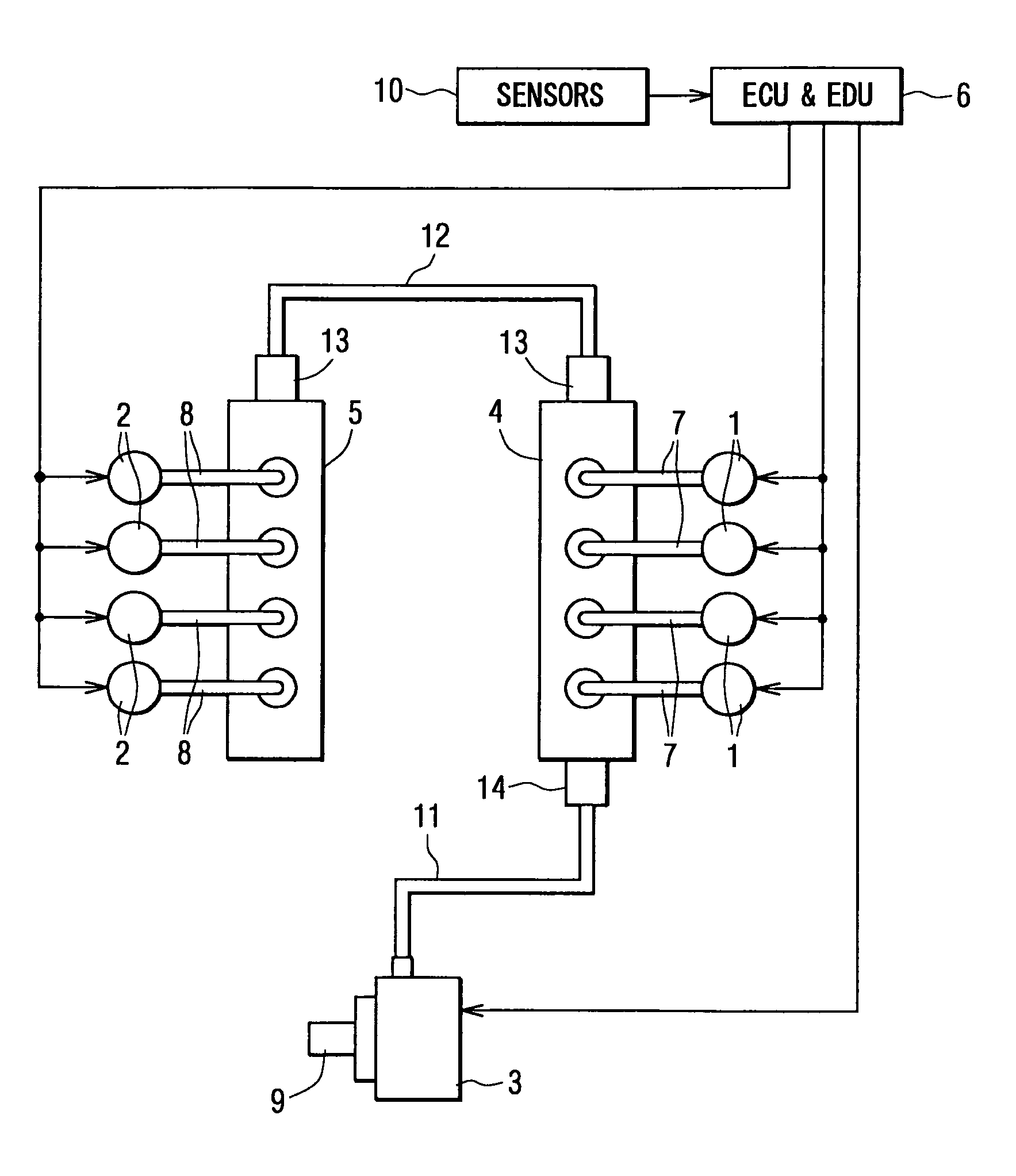
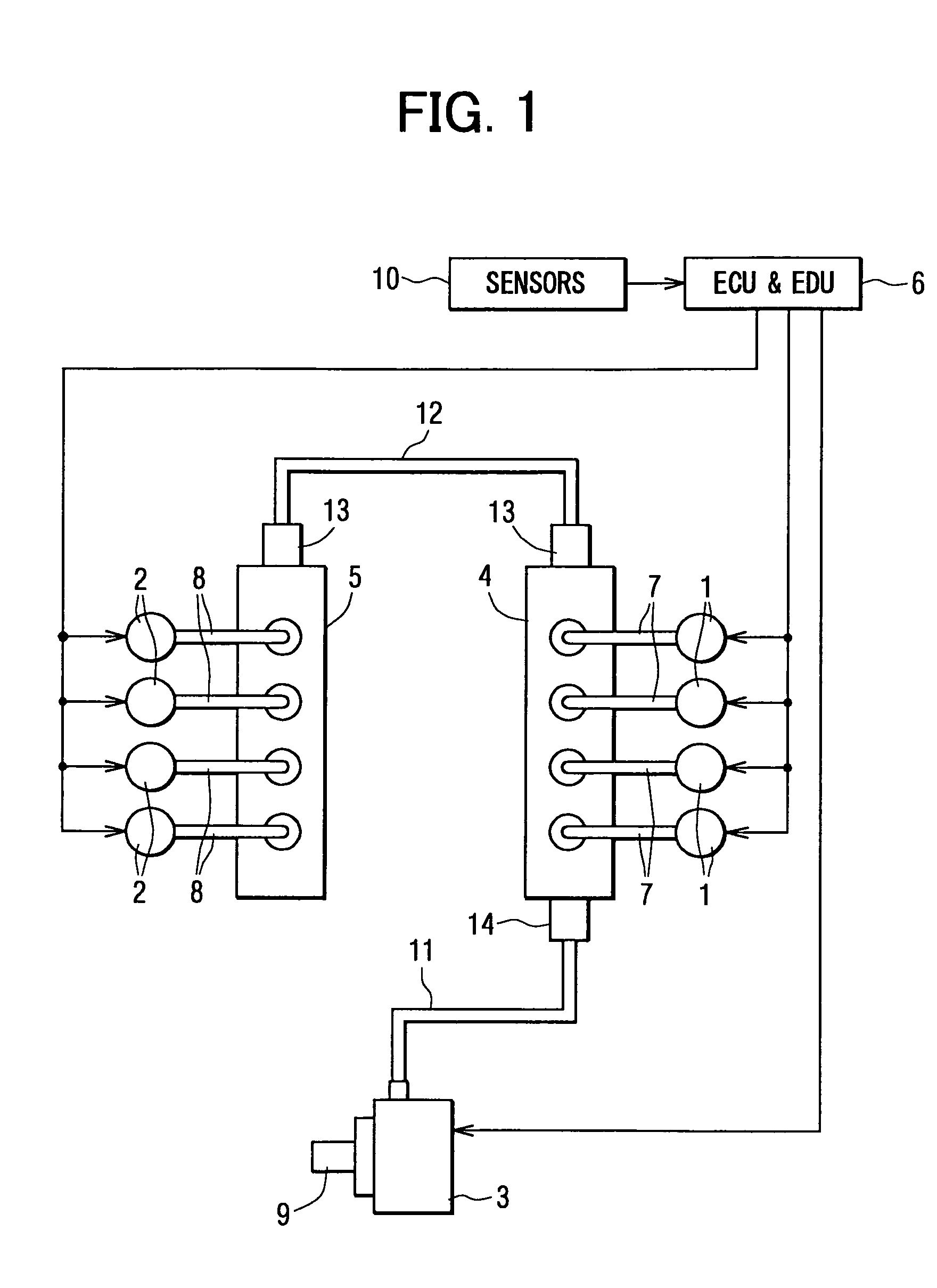
[0020]A first embodiment of the present invention will be described with reference to FIGS. 1–3B. A common-rail-type injection device shown in FIG. 1 is used for an eight-cylinder diesel engine having two lines (two blocks) of cylinders, such as a V-type engine and a parallel-facing-type engine. The fuel injection device is composed of a fuel supply pump 3, a first common rail 4 to which first injectors 1 are connected, a second common rail 5 to which second injectors 2 are connected, an electronic control unit and an electronic drive unit 6, and associated components.

[0021]The first injectors 1 are mounted on a first cylinder line (block) having four cylinders and connected to the first common rail 4 through injector pipes 7. Each first injector 1 injects high-pressure fuel accumulated in the first common rail 4 into each cylinder of the first cylinder line. Similarly, the second injectors 2 are mounted on a second cylinder line (block) having four cylinders and connected to the se...


PUM


Abstract

A fuel injection device for supplying high-pressure fuel to an internal combustion engine includes a fuel supply pump, a first common rail and a second common rail. High-pressure fuel is directly supplied to the first common rail and then to the second common rail from the first common rail through a connecting passage having an orifice. The high-pressure fuel accumulated in the common rails is supplied to injectors and is injected into cylinders in a controlled manner. To suppress pressure wave propagation from the first common rail to the second common rail while providing an appropriate flow passage size, a passage diameter of the orifice is set to 0.9 mm–1.3 mm. In this manner, a pressure difference between the first common rail and the second common rail is minimized.

Description

CROSS-REFERENCE TO RELATED APPLICATION[0001]This application is based upon and claims benefit of priority of Japanese Patent Application No. 2003-399976 filed on Nov. 28, 2003, the content of which is incorporated herein by reference.BACKGROUND OF THE INVENTION[0002]1. Field of the Invention[0003]The present invention relates to a common-rail-type fuel injection device having two separate common rails for supplying high-pressure fuel to an internal combustion engine.[0004]2. Description of Related Art[0005]A common-rail-type fuel injection device having two separate common rails is often used for an internal combustion engine having two cylinder lines, such as a V-type engine or a parallel-facing-type engine. This type of fuel injection device is described, e.g., in an article entitled “Der erste Achtzylinder-Dieselmotor mit Direkteinspritzung von BMW” (authors: Ferenc Anisits, Klaus B. Borgmann, Helmut Kratochwill and Fritz Steinparzer) in “Motortechnische Zeitschrift (MTZ)” issued...

Claims


Application Information

Patent Timeline
Patent Type & Authority Patents(United States)
IPC IPC(8): F02M69/46F02M55/02F02M63/00F02M63/02
CPCF02M55/025F02M2200/315F02M2200/40F02M2200/60
Inventor KAWASAKI, YUSUKESUENAGA, RYOOKI, MAMORU
Owner DENSO CORP
Why Eureka
Try Eureka