
Composite valve for gas supply system

a gas supply system and composite valve technology, applied in the direction of valve details, valve housings, valve arrangements, etc., can solve the problems of gas that goes over the shut-off capacity leaking out of the outflow side, and achieve the effect of compact structure, reduced number of components, and high reliability

Active Publication Date: 2006-11-07
KITZ SCT
View PDF7 Cites 8 Cited by
  • Summary
  • Abstract
  • Description
  • Claims
  • Application Information

AI Technical Summary

Benefits of technology

The present invention provides an automatic-and-manual operation composite valve that has a compact structure, a high reliability, and both pressure-resistance and security features. The valve has a valve body, a piston, and a snapping force of a spring, and a manual operation mechanism portion for switching air supply and air discharge. The valve can be used in a gas supply system for an integrated gas panel, which has a compact size and improves productivity. The valve can also prevent malfunctions and mischief, and is enhanced in safety and operation convenience.

Problems solved by technology

However, in the case of using the prior art composite valve in which the manual operation handle is combined with the automatic operation valve, the following problems have been imposed.
To be specific, when an excessive pressure (1470 Pa or more, for example) is applied to the gas supply side of the valve, the snapping force of the spring of the automatic operation valve cannot restrain a pressing body, the pressure goes over a gas shut-off capacity when the valve is closed, and there is a possibility of the gas leaking out of the outflow side.
Further, since the prior art composite valve has the structure in which the manual operation handle is operated in a state in which supply of the compressed air to the automatic operation valve is not shut off, in case where the pressure in the gas supply side is excessive (1470 Pa or more, for example), there is a possibility of the gas that goes over the shut-off capacity leaking out of the outflow side due to the excessive pressure even when a small amount of air is supplied, because of the presence of inside residual compressed air.

Method used


Image

  • Composite valve for gas supply system
  • Composite valve for gas supply system
  • Composite valve for gas supply system

Examples


Embodiment Construction

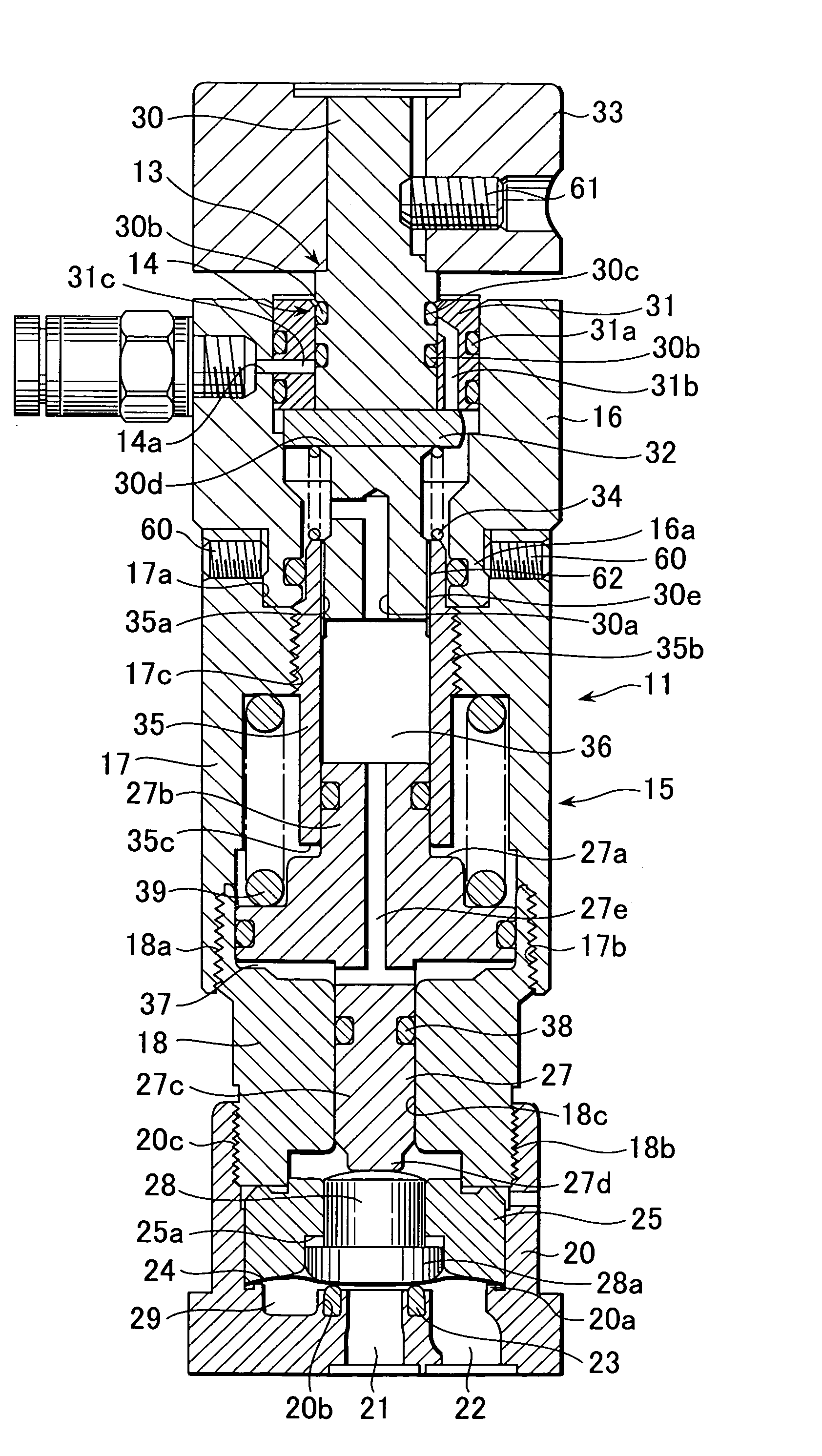
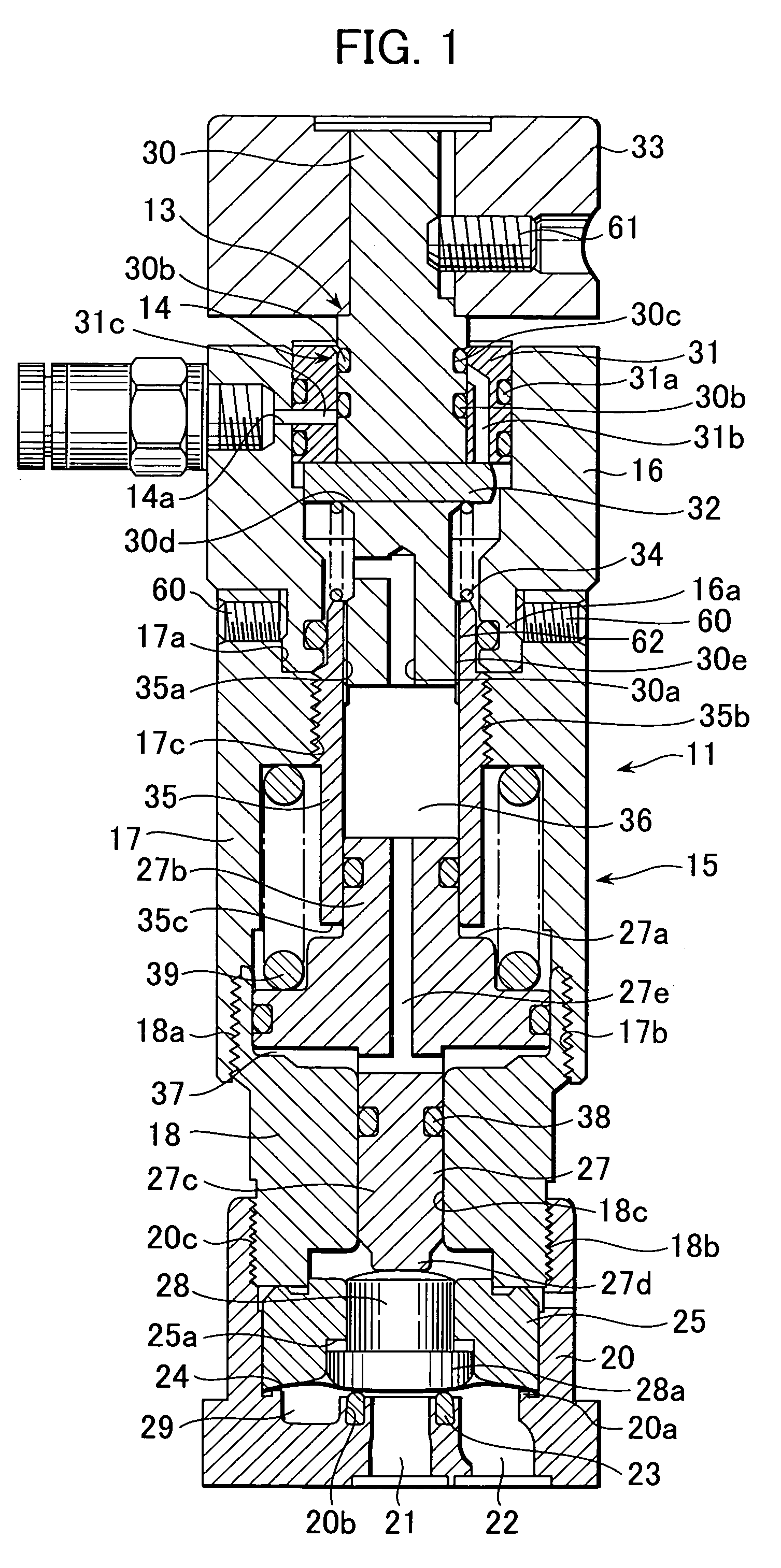
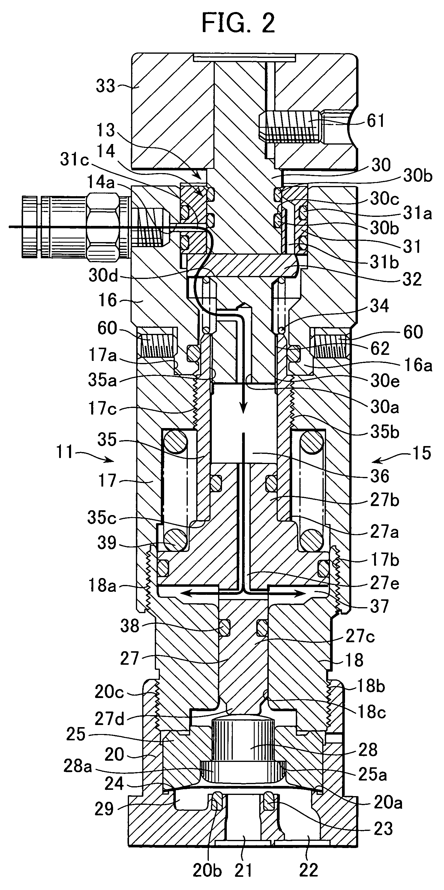
[0036]One embodiment of an automatic-and manual operation composite valve according to the present invention will be described with reference to FIGS. 1 to 3.

[0037]FIG. 1 is a vertical cross sectional view showing the embodiment of the composite valve according to the present invention, in which a valve body comprises a diaphragm.

[0038]In a valve main body 11, a casing 15 comprises an upper casing 16, an intermediate casing 17 and a lower casing 18. An annular protruding portion 16a of the upper casing 16 is fastened and firmly fixed to an annular recess portion 17a of the intermediate casing 17 with a locking screw 60 in a state in which the annular protruding portion 16a is fitted to the annular recess portion 17a. On the other hand, the intermediate casing 17 and the lower casing 18 are firmly fixed to each other by screw engagement between a female thread 17b formed in the intermediate casing 17 and a male thread 18a formed on the lower casing 18. Further, a base 20 is firmly fi...


PUM


Abstract

An automatic-and-manual operation composite valve includes a valve main body into which an air is supplied and from which the air is discharged, a piston provided within the valve main body to be vertically movable by means of the air supplied or discharged and a snapping force of a spring attached to the piston, a valve body provided within the valve main body, and opened and closed by the piston, an air switch valve portion provided within the valve main body for switching air supply and air discharge and a manual operation mechanism portion for operating the air switch valve portion.

Description

BACKGROUND OF THE INVENTION[0001]1. Field of the Invention[0002]The present invention relates to an automatic-and-manual operation composite valve used in an integrated gas supply system for a semiconductor manufacturing apparatus to execute a fluid control.[0003]2. Description of the Prior Art[0004]The integrated gas supply system used for the semiconductor manufacturing apparatus comprises, for example, an integrated gas panel 1 as shown in FIG. 12. In order to control a fluid flow path for the supplied gas, the panel 1 is provided with various valves, a filter 5, a regulator (not shown) or the like in a connectable manner midway of the fluid flow path, and these components can be arranged on a line at a time of being connected. A plurality of such panels are mounted in parallel on a gas supply system (not shown).[0005]A valve for opening and closing the flow path of the panel 1 includes a manual operation valve 2, an automatic operation valve 3, a purge valve 4 and the like. The ...

Claims


Application Information

Patent Timeline
Patent Type & Authority Patents(United States)
IPC IPC(8): F16K31/143F16K31/163F16K31/363F16K31/383F16K31/122B60T17/04F16K27/00
CPCB60T17/04F16K27/003F16K7/17F16K31/1225F16K31/1226
Inventor IWABUCHI, TOSHIAKIFUKATSU, SATORU
Owner KITZ SCT
Learn More