
Backlight apparatus

a backlight and apparatus technology, applied in the field of backlight apparatus, can solve the problems of poor uniformity of light in the whole light guide plate, and achieve the effects of increasing the reflective area, increasing the brightness and uniformity of light, and increasing the reflection

Active Publication Date: 2006-11-07
NANO PRECISION TAIWAN LTD
View PDF18 Cites 47 Cited by
  • Summary
  • Abstract
  • Description
  • Claims
  • Application Information

AI Technical Summary

Benefits of technology

The present invention provides a backlight apparatus with a reflective pattern that has a ring concavity or a ring convexity to increase the reflective area and improve the brightness and uniformity of light. This results in higher brightness and uniformity of the light emitted from the backlight apparatus. The backlight apparatus includes a guiding element and a light source, with the reflective pattern composed of at least one concavity and at least one convexity. The concavity is located at the rim around the convexity. The light source emits light to the guiding element, which increases the reflective area and improves the distribution of brightness.

Problems solved by technology

Thus, light is not reflected or refracted out of the light guide plate effectively and cannot proceed away from the light source, causing the uniformity of light in the whole light guide plate to be not good.

Method used


Image

  • Backlight apparatus
  • Backlight apparatus
  • Backlight apparatus

Examples


Embodiment Construction

[0019]The technical method taken for achieving the above objective and other effects in the present invention are illustrated with drawings in the following two preferred embodiments.

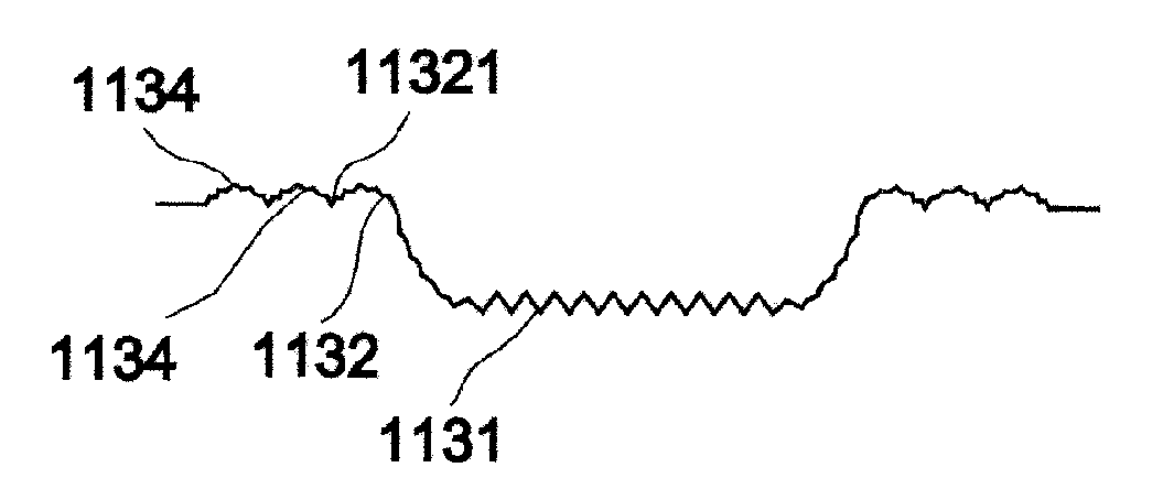
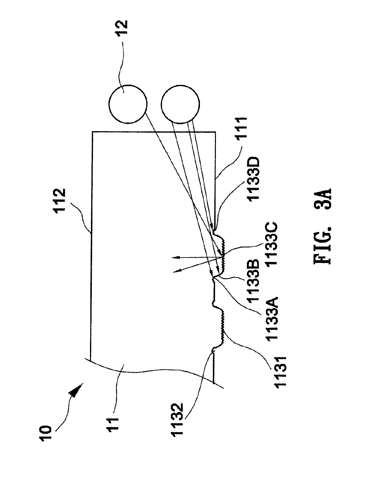
[0020]Please refer to FIG. 3A and FIG. 3B. In the first preferred embodiment, the backlight apparatus 10 includes a guiding element 11 and a light source 12 disposed on at least one lateral side of the guiding element 11. The guiding element 11 has a bottom surface 111 and an emitting surface 112. There is a plurality of reflective patterns 113 disposed on the bottom surface 111. The reflective patterns 113 are distributed with a proper distance between one another on the bottom surface 111. Each reflective pattern 113 is composed of a convexity 1131 and a concavity 1132 disposed at the rim 11311 around the convexity 1131. The shape and size of the convexity 1131 and the concavity 1132 are configured according to the location of the light source. The convexity 1131 is a cylinder, an angular column or a ...


PUM

PropertyMeasurementUnit
diameteraaaaaaaaaa
diameteraaaaaaaaaa
heightaaaaaaaaaa

Abstract

A backlight apparatus includes a guiding element and a light source disposed at one side of the guiding element. There is a plurality of reflective patterns at the bottom surface of the guiding element. Each reflective pattern is composed of at least one concavity and at least one convexity. The concavity is disposed at the rim around the convexity. As the light source emits light to the guiding element, the reflective area is increased by the concavity of the reflective pattern for increasing the reflecting effect and for distributing the brightness more uniformly, and thereby higher brightness and uniformity can be achieved.

Description

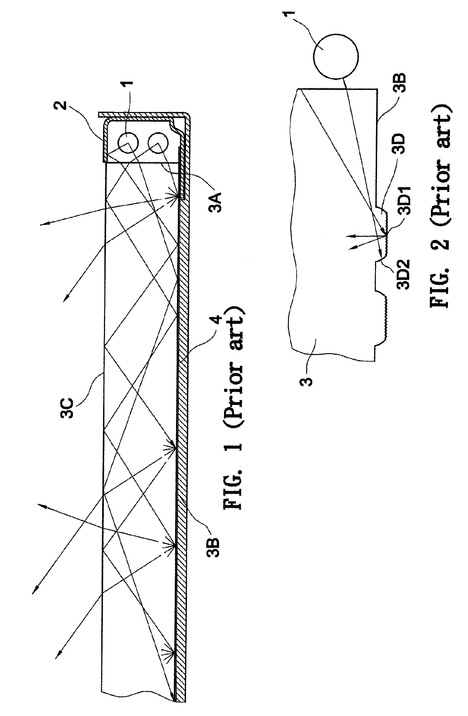
BACKGROUND OF THE INVENTION[0001]1. Field of the Invention[0002]The present invention relates to a backlight apparatus, and more particularly, to a guiding element in the backlight apparatus.[0003]2. Description of the Prior Art[0004]A liquid crystal panel does not emit light itself, and therefore a backlight apparatus is needed for the liquid crystal panel to display images normally.[0005]Please refer to FIG. 1. Conventionally a backlight apparatus of a liquid crystal panel includes a light source 1, a reflector 2, a light guide plate 3 and a reflective plate 4. The light source 1 provides light for the backlight apparatus, and the reflector 2 surrounds the light source 1 for reflecting light provided from the light source 1 into the light guide plate 3. The light guide plate has a front surface 3C and a rear surface 3B. An end 3A of the light guide plate is adjacent to the light source 1 for receiving light from the light source 1. There is a plurality of reflective patterns 3D di...

Claims


Application Information

Patent Timeline
Patent Type & Authority Patents(United States)
IPC IPC(8): F21V7/04F21V8/00G02F1/1335G02F1/13357
CPCG02F1/133615G02B6/0036
Inventor HSU, CHIEN-HUNGHUANG, WEN-YUNGLIU, MING-DAHPAN, BOR-JYH
Owner NANO PRECISION TAIWAN LTD
Learn More