Backflow prevention sleeve for suctioning devices

a suction device and backflow prevention technology, applied in the field of suction devices, can solve the problems of contaminated fluid in the vacuum line, temporary loss of suction flow, cross-contamination of microorganisms, etc., and achieve the effect of preventing cross-contamination of microorganisms

Inactive Publication Date: 2006-11-07
MARCH MICHAEL S
View PDF32 Cites 24 Cited by
  • Summary
  • Abstract
  • Description
  • Claims
  • Application Information

AI Technical Summary

Benefits of technology

[0010]Accordingly, an objective and advantage of the present invention is the convenience, cost-efficiency, and effectiveness of a sleeve that prevents backflow of fluid matter and other contaminants in a dental / medical suctioning apparatus.
[0011]It is another object of the present invention to provide a sleeve that prevents cross-contamination of microbes between patients.
[0012]It is another object of the present invention to provide a sleeve that is disposable and replaceable.
[0013]Another object of the present invention is to provide a sleeve that allows the user of the suctioning device to start, stop, and restart the suctioning device more than one time without having to replace the portion of the suction device that comes into contact with the patient.
[0014]Another object of the present invention is to provide a sleeve that does not require any additional equipment, but can be used with a practitioner's normal evacuation system.
[0015]Another object of the present invention is to provide a sleeve that will not compromise the function of the dental / medical suctioning device.

Problems solved by technology

Such cross-contamination can occur as vacuumed bodily fluids and / or contaminants can backflow from the vacuum line into the patient's mouth / body.
For instance, if the intake is blocked disrupting vacuum flow, the contaminated fluid in the vacuum line may flow down by gravity if the suction device is tilted down toward the patient.
In yet other instances, the vacuum line or hose distal to the vacuum tip and control valve can become obstructed during use creating a temporary loss of suction flow.
However, such valves can be complex, expensive, and difficult to fully clean, disinfect, and sterilize.
Additionally, even if the portion of the suctioning device that comes into contact with the patient during the performed procedure is replaced for each new patient, it is generally too expensive and time-consuming to replace the vacuum hose and control valve.
Regardless of component design, the vacuum hose is difficult to properly clean and sterilize due to temperature and chemical compatibility constraints resulting in residual fluid in the vacuum hose that can lead to the exchange of unwanted and / or dangerous externally introduced fluids from prior patients.
Further, it is very difficult to properly clean (scrub and rinse) contaminants from the inside of a hose, which is needed before it can be effectively disinfected and then sterilized.
Additionally, the control valve attached to the hose is difficult to remove, disassemble, clean, autoclave, and reassemble.
Also, sterilizing the control valve is fruitless after reattaching it to a contaminated hose.
Therefore, when a new disposable / replaceable end of the dental / medical suctioning device is inserted onto the vacuum line, the patient is still at risk of being exposed to backflow or reverse traveling movement of microbes.
Therefore, the current disposable and replaceable parts may provide a sense of false security to patients and practitioners.
Another disadvantage of the prior art with respect to disposable / replaceable parts is that it does not allow the operator to shut-off the vacuum and then restart it without subjecting the patient to cross-contamination from backflow as the evacuator is sloped down into the patient's mouth.
Allowing the vacuum line to suck air from the general room is not a viable option as the portion of the suction device that is inserted into the patient may become contaminated from airborne contaminants.
Further, a vacuum line allowed to suck air from the general room produces an unwanted and annoying hissing noise from the dental / medical suctioning device.

Method used


Image

  • Backflow prevention sleeve for suctioning devices
  • Backflow prevention sleeve for suctioning devices
  • Backflow prevention sleeve for suctioning devices

Examples


Embodiment Construction

[0032]Embodiments of the present invention have wide applications to a number of dental and medical procedures and environments. Therefore, although preferred embodiments of the invention will be described with respect to dental devices and applications, the invention is not limited to these embodiments, but would be equally applicable to other medical applications in which eliminating cross-contamination in vacuum equipment is desired.

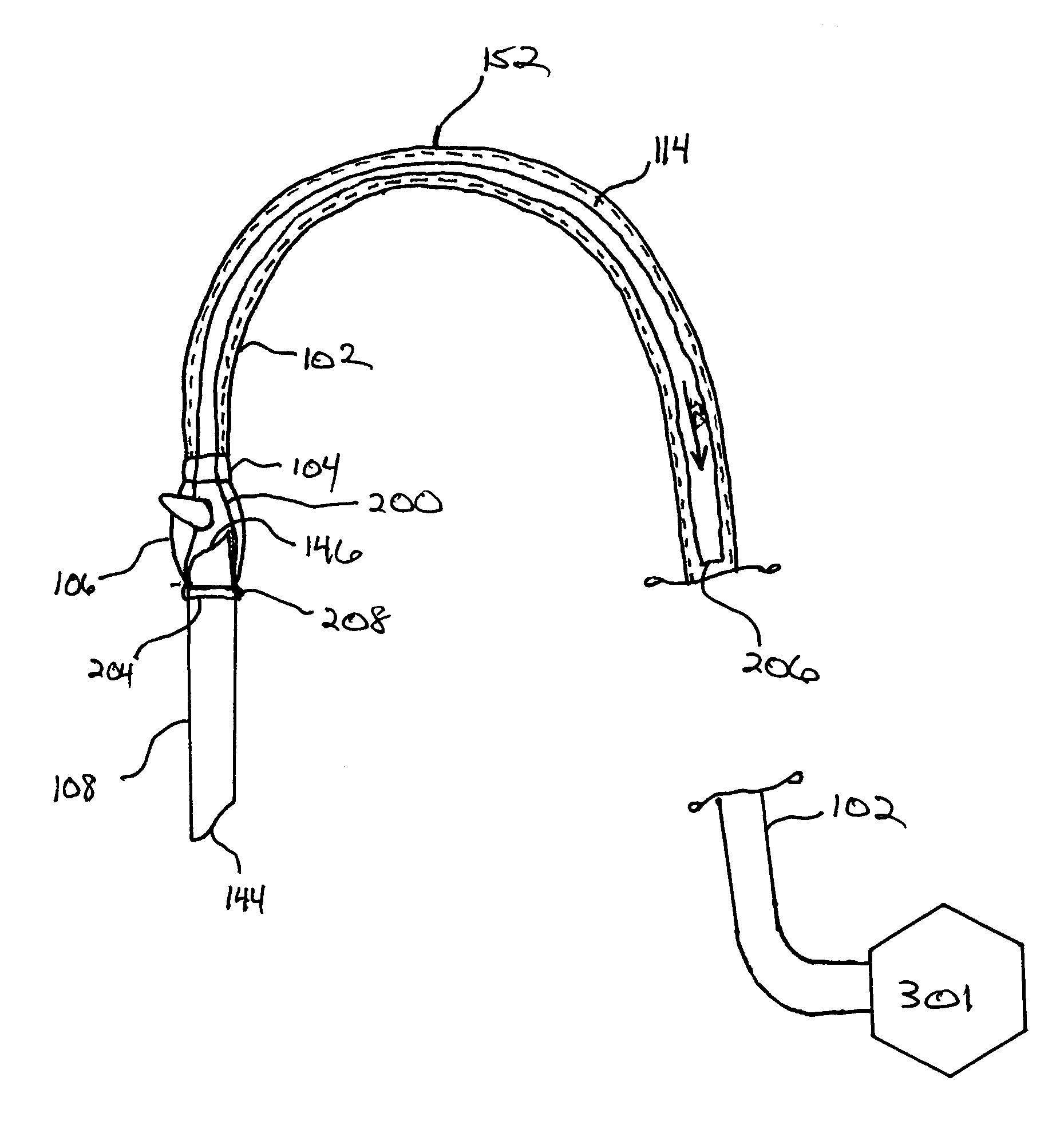
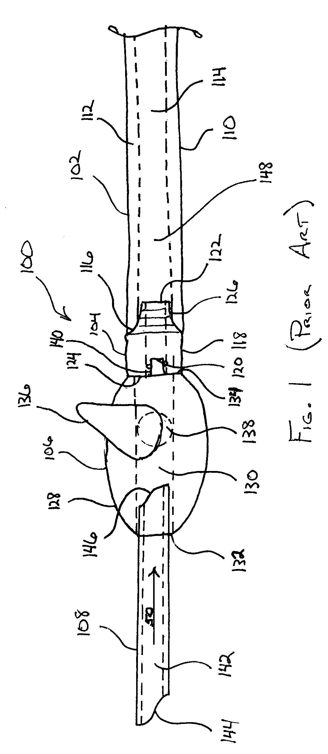
[0033]Referring now to the drawings, there is shown in FIG. 1, a hand-operable suction device 100 as presently used in the practice of dentistry. As illustrated in FIG. 1, the hand-operable suction device 100 comprises a vacuum line 102, a hose adapter 104, a control valve 106 and an evacuator tip 108. Though not depicted, it is to be understood that vacuum line 102 is ultimately fluidly connected to a suction system, i.e. vacuum source, for providing suction through the hand-operable suction device 100 as indicated by the suction flow arrow in FIG. 1...


PUM


Abstract

A sleeve for preventing backflow and cross-contamination between patients of fluid and particulate matter as well as other contaminants present within a dental / medical suctioning device. The sleeve includes a sleeve inlet end that sealingly attaches to and surrounds at least a portion of the suctioning device the vacuum hose to the evacuator tip. The sleeve also has a sleeve exhaust end that is inserted into the control valve and can reside within the interior lumen of the vacuum hose during normal suction operation. During operation, the sleeve provides a seal between the patient contact part and the control valve of the suctioning device. The proximate end collapses, seals, and / or provides a barrier when the suctioning device does not draw a vacuum away from the patient and towards the vacuum source.

Description

PRIORITY CLAIM[0001]The present application claims priority to U.S. Provisional Application No. 60 / 543,789 filed Feb. 11, 2004, and entitled, “BACKFLOW PREVENTION SLEEVE FOR SUCTIONING DEVICES,” which is herein incorporated by reference to the extent not inconsistent with the present disclosure.FIELD OF THE INVENTION[0002]The invention relates generally to suction devices used in healthcare and health maintenance. More particularly, the invention relates to a sleeve for use with dental and medical suction devices that prevents cross-contamination or cross-exposure of various types of fluid and particulate matter as well as other contaminants between patients.BACKGROUND OF THE INVENTION[0003]Suction systems are commonly used in dental practices, medical clinics, hospitals, and other medical operations to remove contaminated debris consisting daily in the dental office of: saliva, food debris, tarter, stain, dental bacterial plaque, tooth debris, filling debris, mucous, phlegm, blood,...

Claims


Application Information

Patent Timeline
Patent Type & Authority Patents(United States)
IPC IPC(8): A61C17/14A61C17/06
CPCA61C17/043A61C17/08
Inventor MARCH, MICHAEL S.
Owner MARCH MICHAEL S
Why Eureka
Try Eureka