Medical fluid collection and removal device

a technology for medical fluids and liquid collectors, which is applied in the direction of liquid handling, application, packaging goods, etc., can solve the problems of increasing floor slipperiness and interfering with surgical procedures, and achieve the effect of convenient handling

Inactive Publication Date: 2006-11-07
TYPENEX MEDICAL
View PDF48 Cites 33 Cited by
  • Summary
  • Abstract
  • Description
  • Claims
  • Application Information

AI Technical Summary

Benefits of technology

[0008]It is another object to provide an easily handled, as for example foldable, tray str...

Problems solved by technology

This increases floor slipperiness ...

Method used


Image

  • Medical fluid collection and removal device
  • Medical fluid collection and removal device
  • Medical fluid collection and removal device

Examples


Embodiment Construction

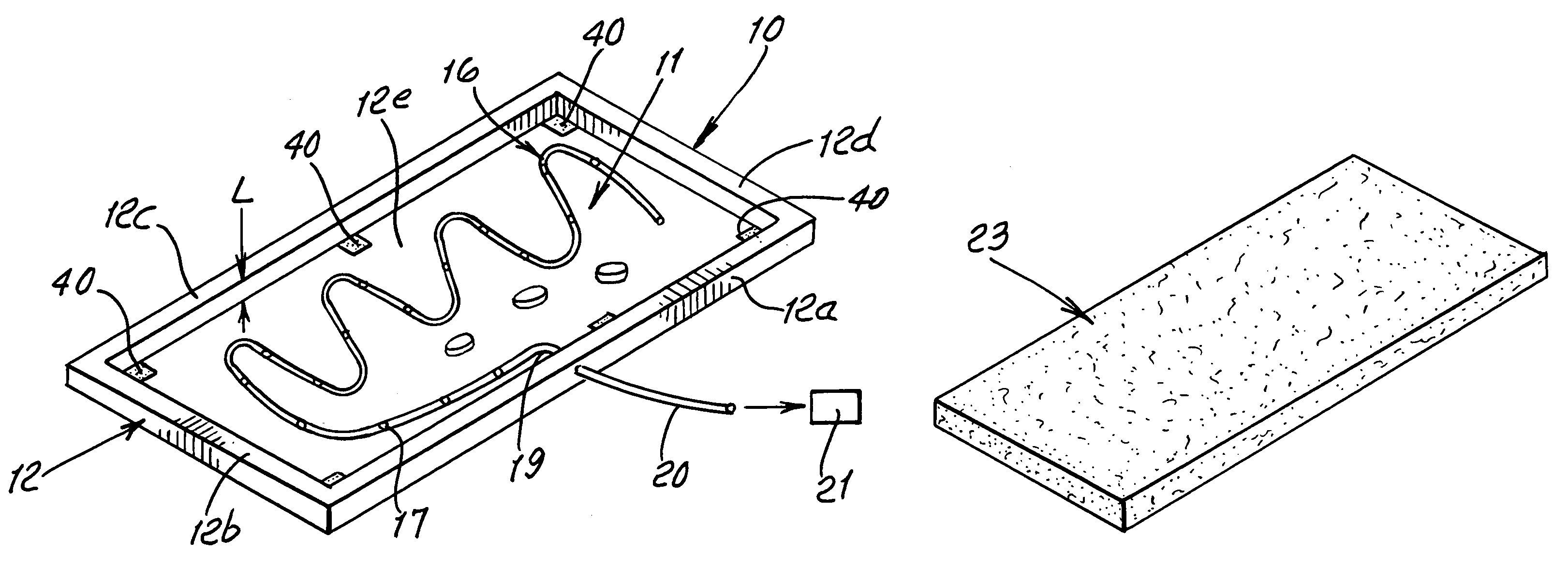
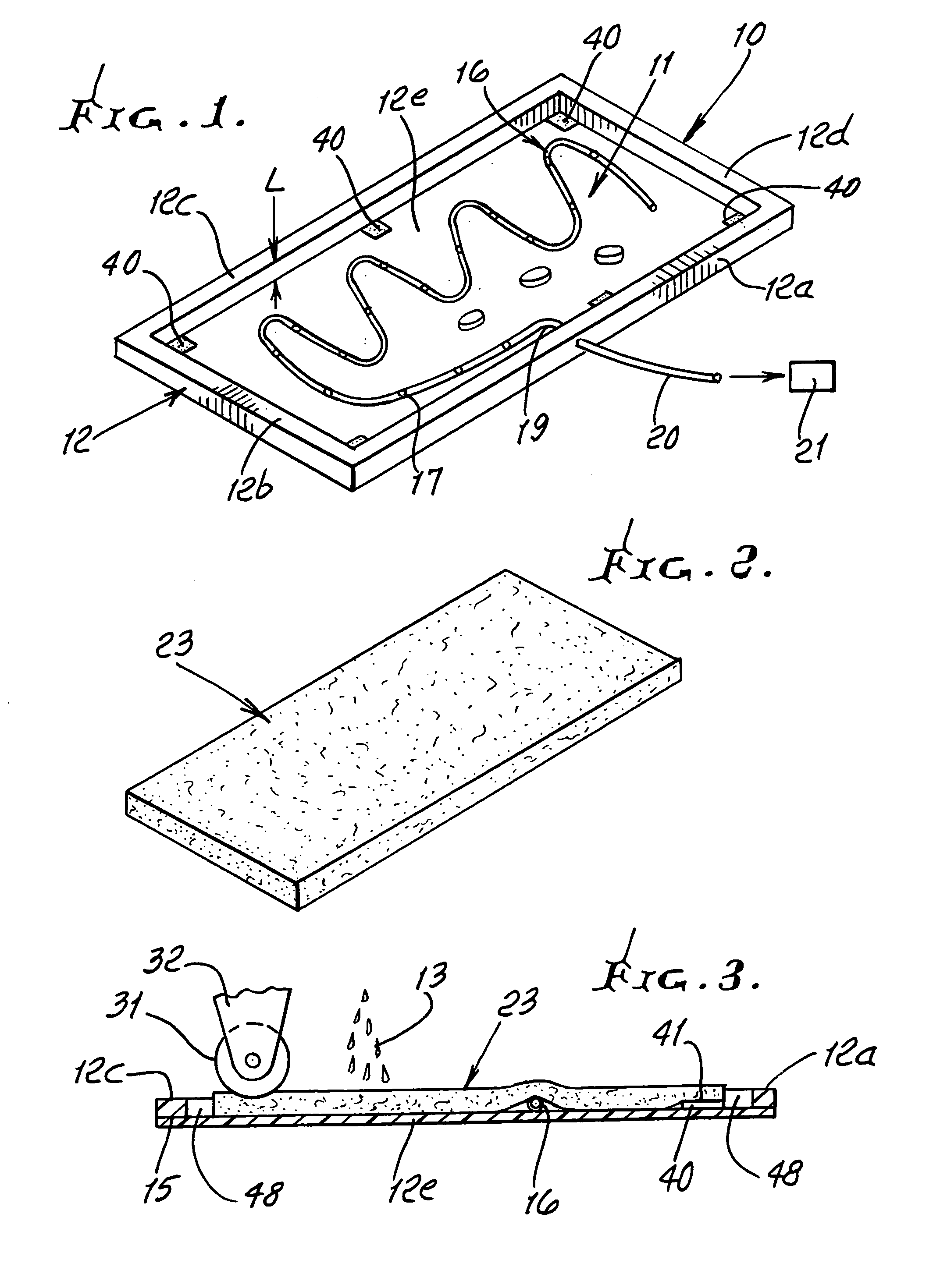
[0021]FIG. 1 shows a preferred shallow tray 10 defining a liquid receiving zone 11 bounded by a peripheral wall 12 defining side wall stretches 12a–12d. Shallow zone is upwardly exposed for receiving liquid dropping from a surgery area, i.e. an operating table. Such liquid typically includes water and body fluid as indicated at 13 in FIG. 3, dropping toward the tray. The tray preferably consists of lightweight flexible plastic foam, enabling easy folding for removal and disposal. Closed cell polyethylene foam is preferred. Wall stretches 12a–12d extend peripherally across the tray thin flat bottom wall 12e, and have overall height “L” above the top of bottom wall 12e less than about 1 inch. Side wall stretches may be bonded as at 15 to the bottom wall.

[0022]Also shown in FIG. 1 is a liquid collection tube 16 extending or lying generally horizontally in zone 11, as on the top surface of bottom wall 12e. The tube outer diameter is less than the height of the wall stretches, to enable ...


PUM

PropertyMeasurementUnit
Lengthaaaaaaaaaa
Lengthaaaaaaaaaa
Digital informationaaaaaaaaaa

Abstract

Liquid collection apparatus usable during surgery, comprising a shallow tray defining a liquid receiving zone that is upwardly exposed for receiving liquid dropping from a surgery area, and a liquid collector in a zone for collecting dropping liquid while allowing a surgeon to tread over a collector, during surgery.

Description

[0001]This application claims priority over provisional application Ser. No. 60 / 341,501, filed Dec. 20, 2001.BACKGROUND OF THE INVENTION[0002]This invention relates generally to liquid collection apparatus usable during surgery to collect liquid drainage from the surgery area; and more particularly concerns an easily manipulated liquid collection tray and liquid collector in the tray allowing surgeon treading over the collector.[0003]During surgery, liquid such as sterile water supplied or used as irrigation liquid is commonly allowed to drain to the floor and collects there. This increases floor slipperiness and interferes with surgical procedures. There is need for improvements in such collection and disposal methods, as well as ease of handling and manipulation of collection and disposal apparatus, as well as ease of rolling travel of operating room heavy equipment over such apparatus, and need for foot comfort of persons standing in such a surgery area.SUMMARY OF THE INVENTION[0...

Claims


Application Information

Patent Timeline
IPC IPC(8): A61B19/00A47K3/02A61M27/00
CPCA61M1/008Y10T137/5762A61M1/84
Inventor THORNBURY, THOMAS R.CHOKSI, PRADIP V.RYAN, JULIE A.
Owner TYPENEX MEDICAL
Why Eureka
Try Eureka