

Ultrasonic surgical instrument
- Summary
- Abstract
- Description
- Claims
- Application Information
AI Technical Summary
Benefits of technology
Problems solved by technology
Method used
Image

Examples
first embodiment
[0088]the present invention will now be described with reference to FIGS. 1 to 13. According to the present embodiment, there is provided an ultrasonic surgical instrument system, which includes ultrasonic surgical instruments of a plurality of types having different tip shapes. A set of these instruments is completed in advance in carrying out ultrasonic treatment such as incision, ablation, or coagulation of organic tissues by utilizing ultrasonic waves. In this system, the surgical instruments are properly used according to the region to be treated and the method of treatment.
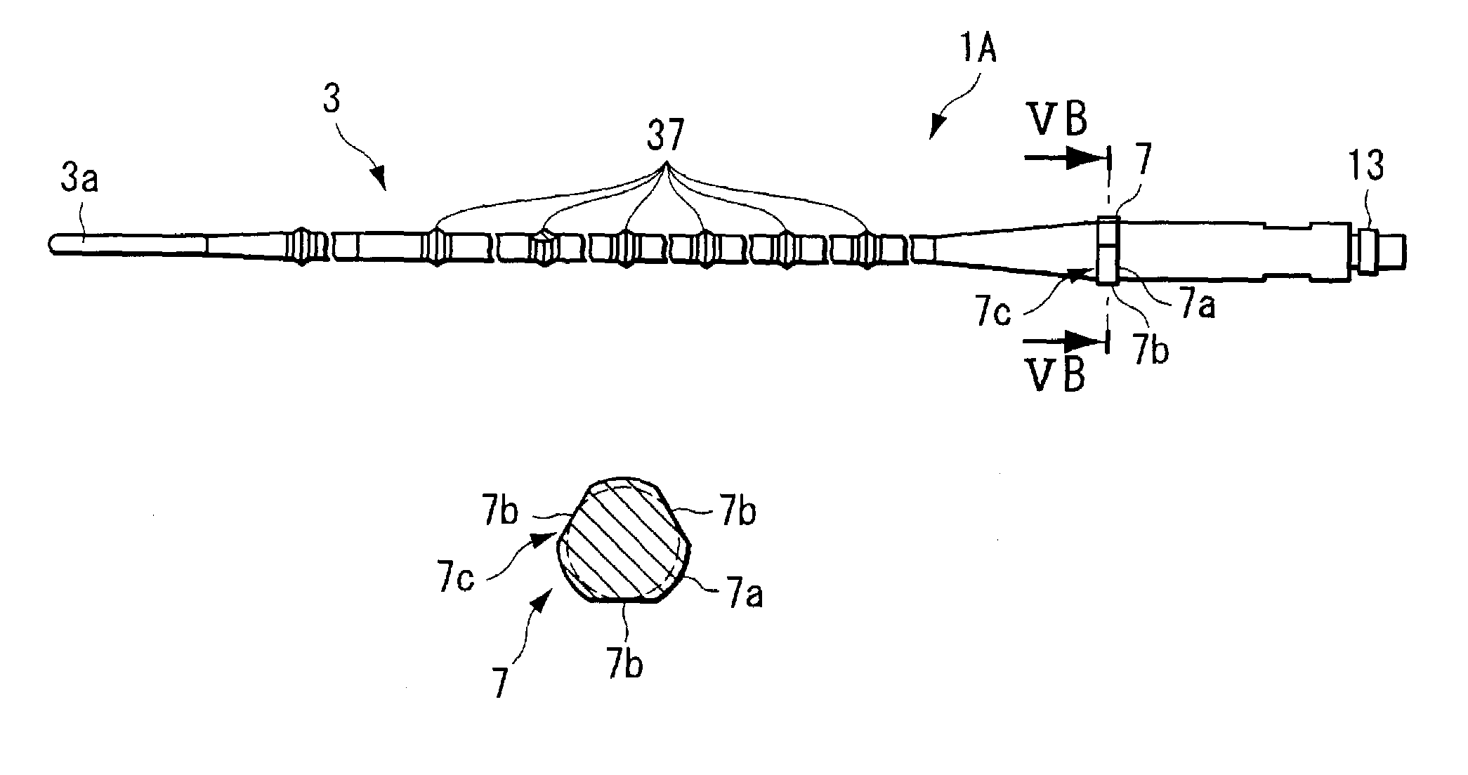
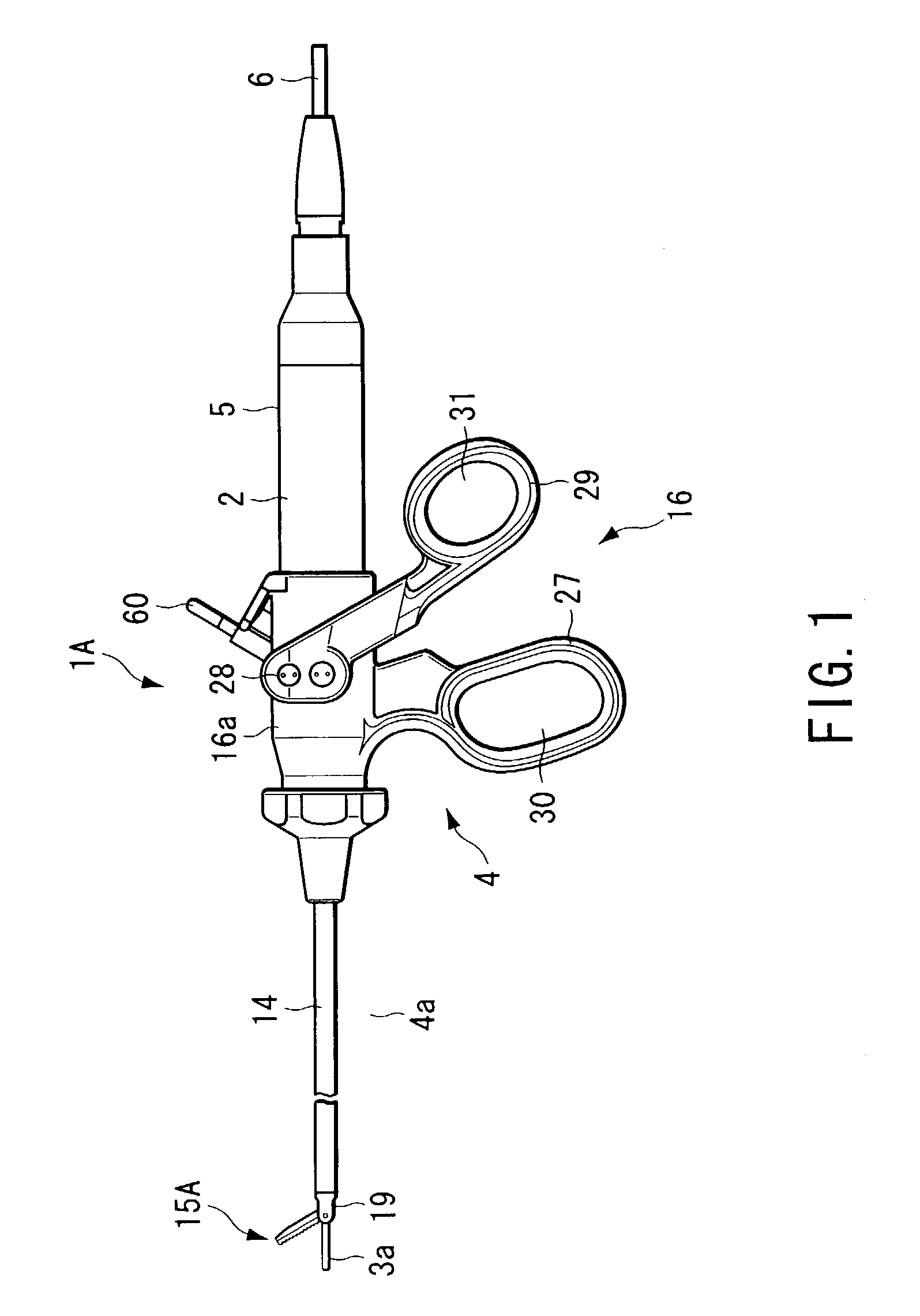
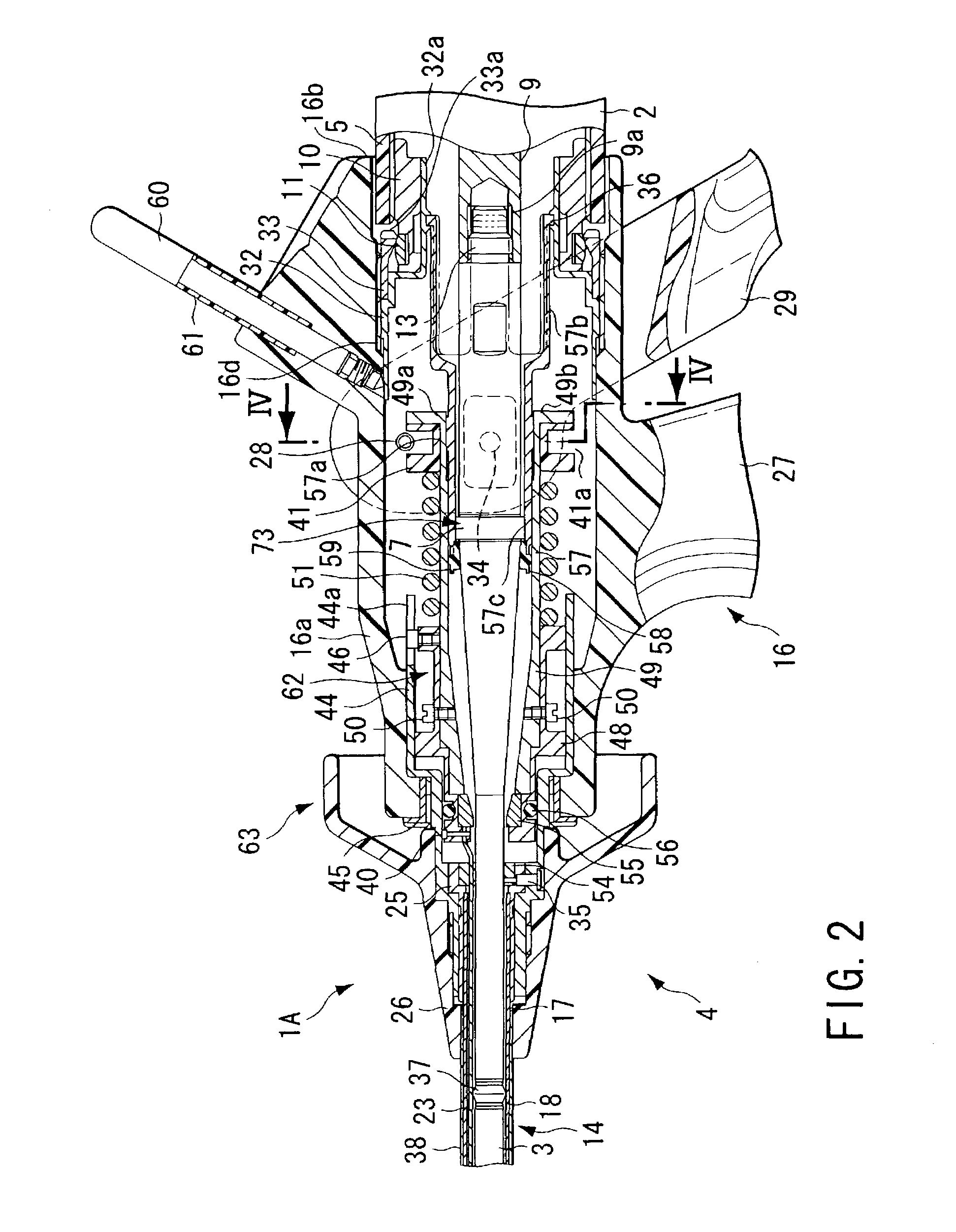
[0089]According to this system, a first ultrasonic surgical instrument 1A shown in FIGS. 1 to 7B and a second ultrasonic surgical instrument 1B shown in FIGS. 8A to 12B are prepared in advance. The first and second ultrasonic surgical instruments 1A and 1B are properly used according to the region to be treated and the method of treatment.
[0090]FIG. 1 shows the first ultrasonic surgical instrument 1A of the ...
second embodiment
[0150]FIGS. 14 to 32 show the present invention. According to the second embodiment, the sheath unit 4 of the first ultrasonic surgical instrument 1A of the first embodiment (see FIGS. 1 to 13) can be further disassembled into a tip unit 81 and a control section unit 82, as shown in FIG. 15. FIGS. 16A and 16B to 22 show the tip unit 81, and FIGS. 23 to 29 show the control section unit 82.
[0151]The tip unit 81 is provided with an elongated insertion section 83 to be inserted into the body cavity in operation. A jaw 84 for use as a distal working section is provided on the distal end portion of the insertion section 83. Further, the proximal end portion of the insertion section 83 is provided with a unit coupling portion 98 (mentioned later) that is detachably coupled to the control section unit 82.
[0152]In the tip unit 81 of the second embodiment, the insertion section 83 has the same construction as the sheath unit 4 of the first embodiment. The jaw 84 of the tip unit 81 of the pres...
PUM
 Abstract
Description
Claims
Application Information