
Transducer for converting between mechanical vibration and electrical signal

a transducer and mechanical vibration technology, applied in the field of acoustic magnetic transducers, can solve the problems of limiting the amount and quality of vibrational damping in the transducer, and achieve the effect of limiting the amount and quality of vibrational damping

Active Publication Date: 2006-11-07
TAYLOR LISTUG
View PDF18 Cites 32 Cited by
  • Summary
  • Abstract
  • Description
  • Claims
  • Application Information

AI Technical Summary

Benefits of technology

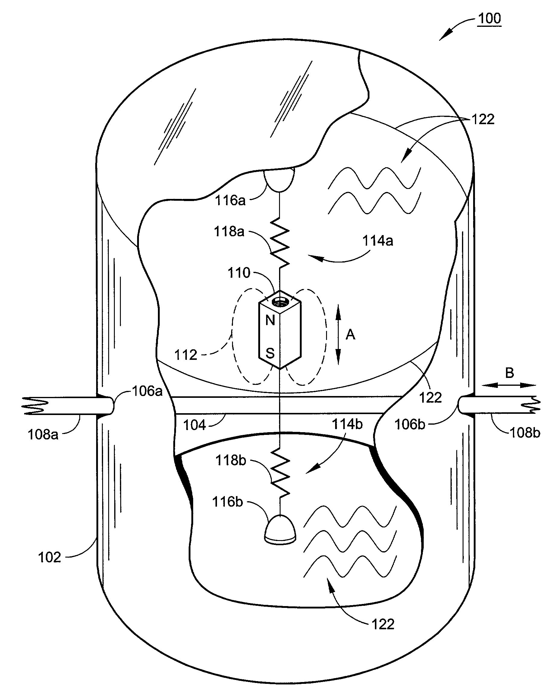
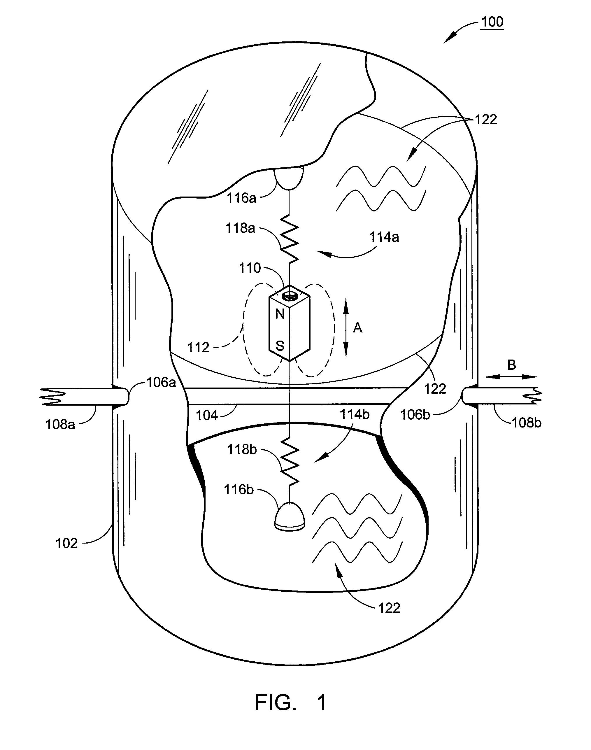
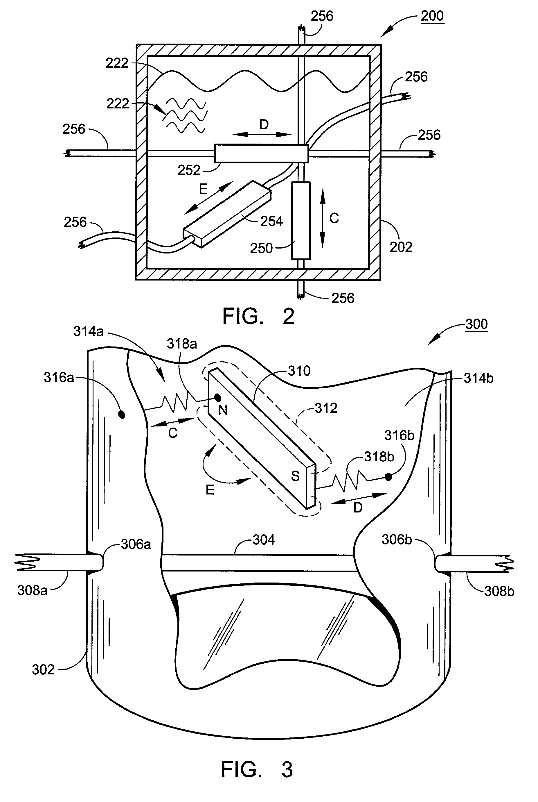
[0010]With the liquid damping aspect of the present invention, the use and careful selection of damping liquids can be used to better control the acoustic characteristics of microphones and speakers employing the transducer. Also, because damping can be supplied as necessary by the damping liquid, there is no need to try to effect damping through any elastic members that constrain the moving component(s) to the housing. In this way, the desired spring force characteristics of the moving component(s) can be adjusted relatively independently of the desired damping.
[0011]In the area of acoustic transducers, and especially transducers for picking up vibrations of a guitar, the design flexibility provided by damping liquid and / or rotational vibration can help optimize sound quality characteristics, including characteristics in the following areas: (1) feedback; (2) attack; (3) sustain; (4) equalization; and (5) Dynamic Range. While there are words to describe sound quality characteristics, judgments about what sound quality is ultimately better or worse is necessarily artistic, subjective and context driven. However, by providing more options for variations in sound quality, a greater number of musical artists and listeners will be able to achieve the sound quality that is respectively more optimal for them and their particular acoustic expressions.

Problems solved by technology

This limited air-and-spring damping limits the amount and quality of the vibrational damping in the transducer.

Method used


Image

  • Transducer for converting between mechanical vibration and electrical signal
  • Transducer for converting between mechanical vibration and electrical signal
  • Transducer for converting between mechanical vibration and electrical signal

Examples


Embodiment Construction

[0026]Before starting a description of the Figures, instructions for interpreting the words and phrases of this patent document will be provided. More particularly, many jurisdictions allow a patentee to act as its own lexicographer, and thereby allow the patentee to provide instructions in a patent document as to how the words, terms and phrases of the document are to be interpreted as a legal matter. For example, in the United States, the prerogative of the patentee to act as its own lexicographer has been solidly established based on statutory and case law. Accordingly, the following section provides rules for interpreting the words, terms and phrases the claims of this patent document.

[0027]Interpretive Rules

[0028]Rule 1: There is a “Specially Defined Terms” section set forth below. Only words, terms or phrases that are explicitly defined in the Specially Defined Terms are to be considered to have a special definition, and, of course, the explicit definition provided herein is t...


PUM


Abstract

Transducer (100, 200, 300, 500, 600) for converting mechanical vibrations to an electrical signal and / or for converting an electrical signal to mechanical vibration. Damping liquid (122, 222, 522, 622) damps the relative vibration of transducer components (110, 250, 252, 254, 510, 610). The damping liquid can be selected to optimize the sound quality of acoustic vibrations at the point of transduction. Also, a transducer with components that rotate relative to each other (304, 310, 504, 510, 604, 610). For example, a permanent magnet component may simultaneous vibrate rotationally and linearly with respect to an electric signal carrying coil. The characteristics of the rotational vibration may be adjusted to optimize sound quality of acoustic vibrations at the point of transduction.

Description

FIELD OF THE INVENTION[0001]The present invention is directed to acoustic-magnetic transducers, and more particularly to acoustic-magnetic transducers for use in musical instruments, such as guitars.BACKGROUND OF THE INVENTION[0002]It has long been recognized that electrical current will induce a magnetic field, and that a moving magnetic field can induce current, or changes in the magnitude of a pre-existing current. One conventional application of this phenomenon is the transducer for converting between current and vibration. More particularly, a transducer for converting between vibration and current can: (1) convert linear mechanical vibration (e.g., acoustic vibration) into a pattern of variations in electrical current; and / or (2) convert variations in a current into vibration. One type of transducer is an accelerometer, which uses the acceleration characteristics of mechanical vibrations in its transduction between vibration and electrical signal.[0003]Generally speaking, the ...

Claims


Application Information

Patent Timeline
IPC IPC(8): G10H3/00G10H3/14G10H3/18
CPCG10H3/146G10H3/181G10H2220/401
Inventor HOSLER, DAVID LEE
Owner TAYLOR LISTUG
Learn More