Circuit for minimizing filter capacitance leakage induced jitter in phase locked loops (PPLs)

a phase locked loop and filter capacitor technology, applied in the field of phased locked loops (plls), can solve the problems of exponential increase in leakage current, problem of leakage current through gate dielectric, and associated penalty, and achieve the effect of minimizing the leakage-induced jitter of filter capacitors

Active Publication Date: 2006-11-07
TAIWAN SEMICON MFG CO LTD
View PDF3 Cites 10 Cited by
  • Summary
  • Abstract
  • Description
  • Claims
  • Application Information

AI Technical Summary

Benefits of technology

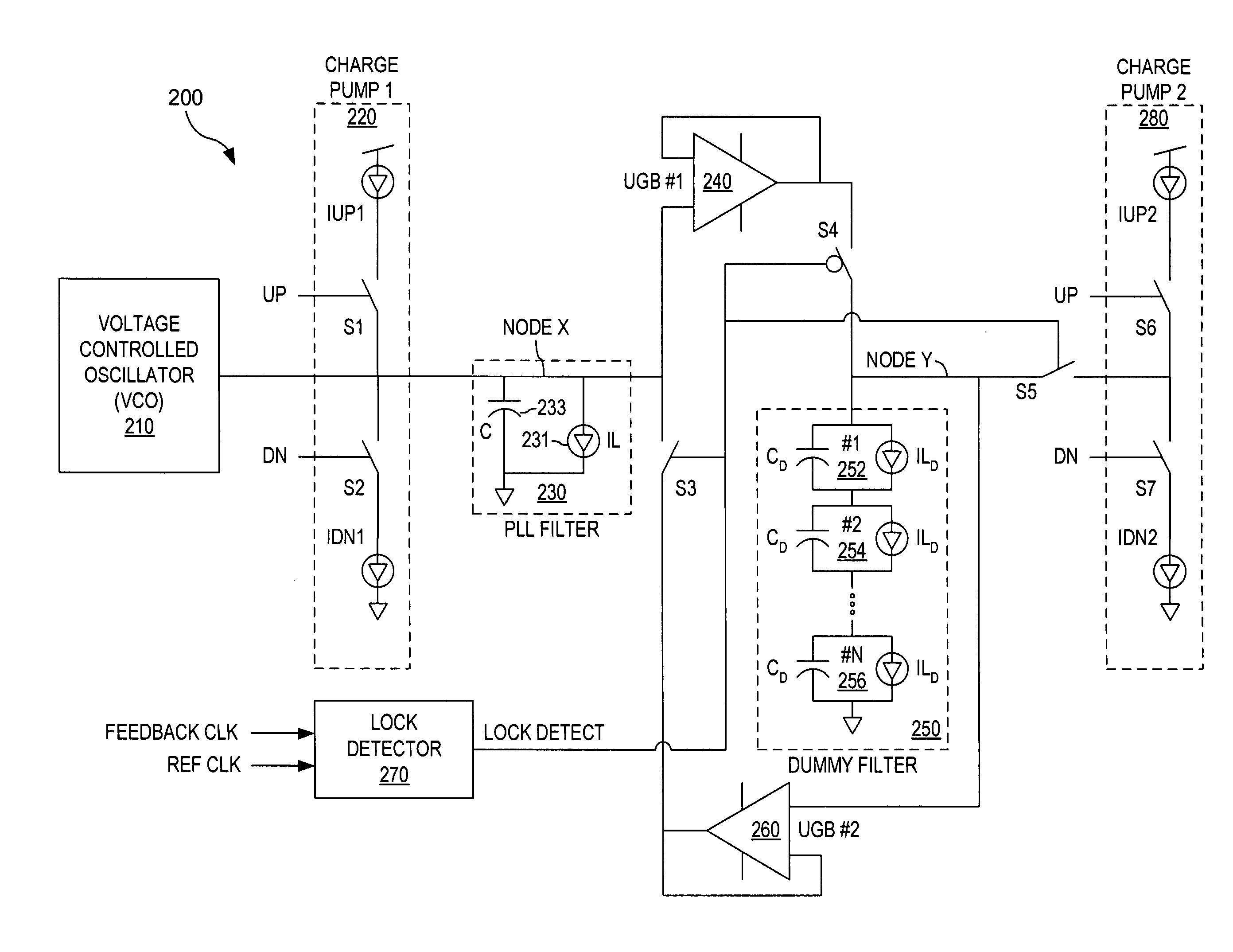
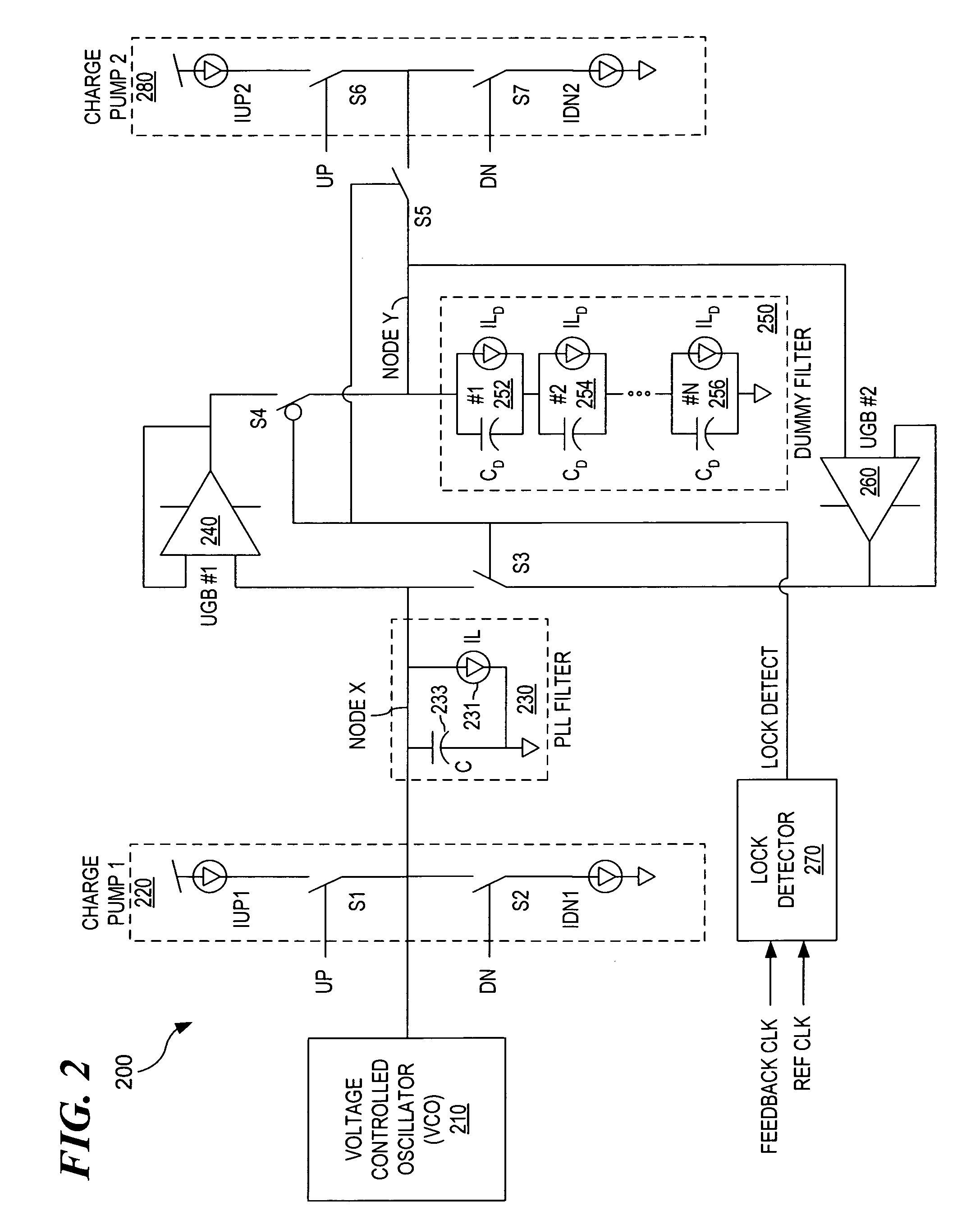
[0013]The present invention provides a method, an apparatus and a computer program for minimizing filter capacitor leakage-induced jitter in a Phased Locked Loop (PLL). As with normal operation of PLL, the PLL attempts to achieve phase and frequency lock with a reference clocking signal. During these periods in and out of phase / frequency lock, a determination is made to see if the PLL is in lock. When not locked, capacitors in the dummy filter are charged. Then when in frequency lock, the capacitors in the dummy filter are discharged to exponentially slow the rate of decay of the voltage across the Low Pass Filter as a result of current leaks.

Problems solved by technology

However, with the rapid advancement of CMOS technology and the resulting reduction of the gate oxide thickness, a regime is being entered wherein the effect of leakage current through the gate dielectric is a problem.
Also, increasing the voltage across the capacitor will result in an exponential increase in leakage current.
However, the penalty for this is the associated exponential increase in leakage current.
However, the addition of this resistor reduces the effective dominant pole frequency of the PLL, thereby reducing PLL bandwidth.
However, while long-term jitter is filtered out, the output of the VCO can suffer from substantial cycle-to-cycle jitter.

Method used


Image

  • Circuit for minimizing filter capacitance leakage induced jitter in phase locked loops (PPLs)
  • Circuit for minimizing filter capacitance leakage induced jitter in phase locked loops (PPLs)
  • Circuit for minimizing filter capacitance leakage induced jitter in phase locked loops (PPLs)

Examples


Embodiment Construction

[0019]In the following discussion, numerous specific details are set forth to provide a thorough understanding of the present invention. However, those skilled in the art will appreciate that the present invention may be practiced without such specific details. In other instances, well-known elements have been illustrated in schematic or block diagram form in order not to obscure the present invention in unnecessary detail. Additionally, for the most part, details concerning network communications, electromagnetic signaling techniques, and the like, have been omitted inasmuch as such details are not considered necessary to obtain a complete understanding of the present invention, and are considered to be within the understanding of persons of ordinary skill in the relevant art.

[0020]It is further noted that, unless indicated otherwise, all functions described herein may be performed in either hardware or software, or some combinations thereof. In a preferred embodiment, however, the...


PUM


Abstract

A method, an apparatus, and a computer program are provided to minimize filter capacitor leakage in a Phased Locked Loop (PLL). In high frequency processors and devices, filter leakage currents can cause substantial problems by causing PLLs to drift out of phase lock. To combat the leakage currents, a dummy filter and other components are employed to provide additional charge or voltage to a low pass filter during lock. The provision of the charge or voltage exponentially decreases the rate of decay of voltage across the low pass filter caused by leakage currents.

Description

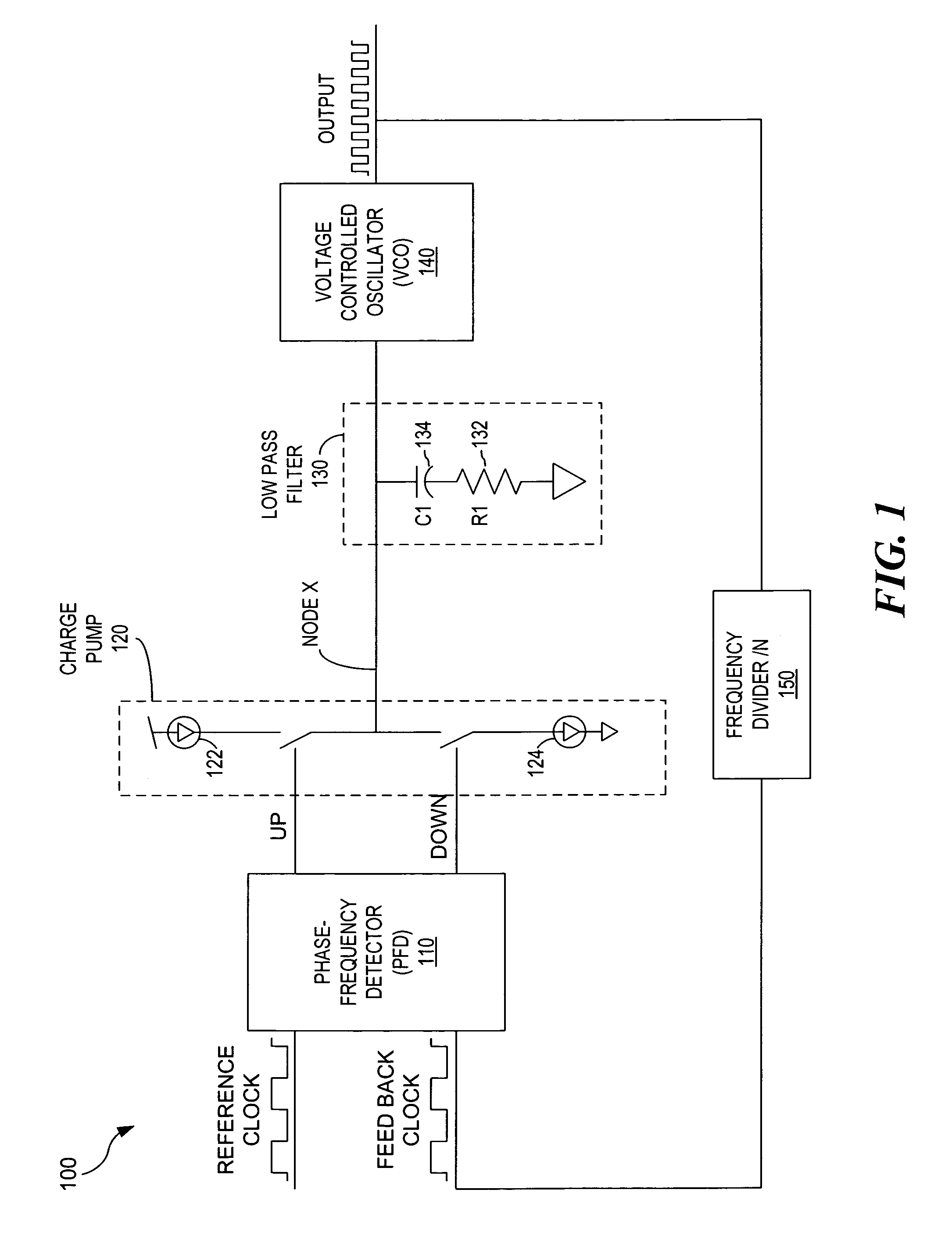
FIELD OF THE INVENTION[0001]The present invention relates generally to Phased Locked Loops (PLLs) and, more particularly, to reducing leakage current across low pass filters of PLLs in high frequency systems.DESCRIPTION OF THE RELATED ART[0002]PLLs can be an integral component of systems that use clocking for various operations. These systems can include microprocessors, wireless / wireline transceivers, and other devices known to those of skill in the art. Generally, PLLs are used to generate an output waveform which has a timing relationship with an input waveform, such as a 1:1 ratio, a 2:1 ratio, and so on. For instance, an input waveform of 60 Hertz could be inputted into a PLL to generate an output waveform of 120 Hertz. Furthermore, there would be a predefined phase relationship between the input wave and the output wave.[0003]One important element of a PLL is a low pass filter, which typically comprises passive elements, such as capacitors and resistors. In a PLL, the voltage ...

Claims


Application Information

Patent Timeline
Patent Type & Authority Patents(United States)
IPC IPC(8): H03L7/093H03B1/04H03L7/095
CPCH03L7/0893H03L7/093H03L7/095
Inventor BOERSTLER, DAVID WILLIAMHAILU, ESKINDERQI, JIEMING
Owner TAIWAN SEMICON MFG CO LTD
Why Eureka
Try Eureka