CNC slitter machine

Inactive Publication Date: 2006-11-14
HERR VOSS STAMCO INC
View PDF31 Cites 33 Cited by
  • Summary
  • Abstract
  • Description
  • Claims
  • Application Information

AI Technical Summary

Benefits of technology

[0018]As a result of the various embodiments of this invention, a slitting machine is easily and efficiently set up and reconfigured by an operator through the HMI interface, programmable logic controller and knife holder position adjustment system for slitting mults of various sizes without significant machine downtime and labor-intensive procedures. Furthermore, the machine is

Problems solved by technology

Setting the knives on the arbors of a slitting machine however is a tedious and time-consuming procedure, requiring a high degree of skill, for the knives must be located with considerable precision, not only to acquire the proper width for the cut, but to also maintain a clean high quality cut as well.
These spacers are large enough and are machined with enough precision to minimize the wobble inherent with conventional arbo

Method used


Image

  • CNC slitter machine
  • CNC slitter machine
  • CNC slitter machine

Examples


Embodiment Construction

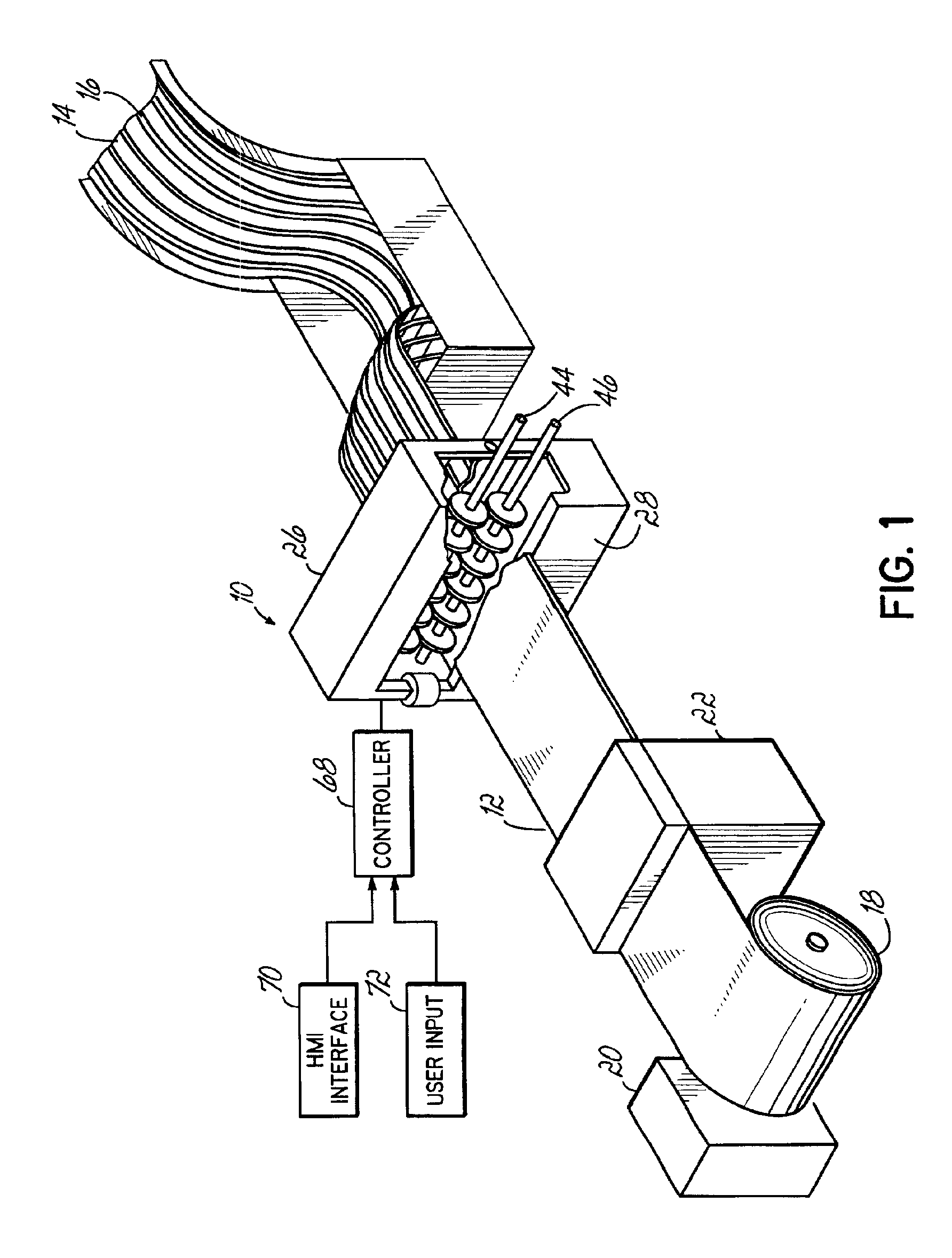
[0032]Referring to FIG. 1, a slitting machine 10 according to a presently preferred embodiment of this invention is used for shearing metal sheet 12, such as sheet steel, into multiple segments or mults 14 of a desired width along slits 16. The metal sheet 12 is normally provided from a mill or other supplier of mill products in a coil 18. The coil 18 is supported on a spool 20. The metal sheet 12 is withdrawn from the coil 18 and fed into the machine 10. Typically, the metal sheet 12 passes through a straightening machine 22 to remove the coil set. The sheet 12 alternatively may be fed into the machine 10 in individual sections, preferably with the assistance of a skewed roller table (not shown) or the like.

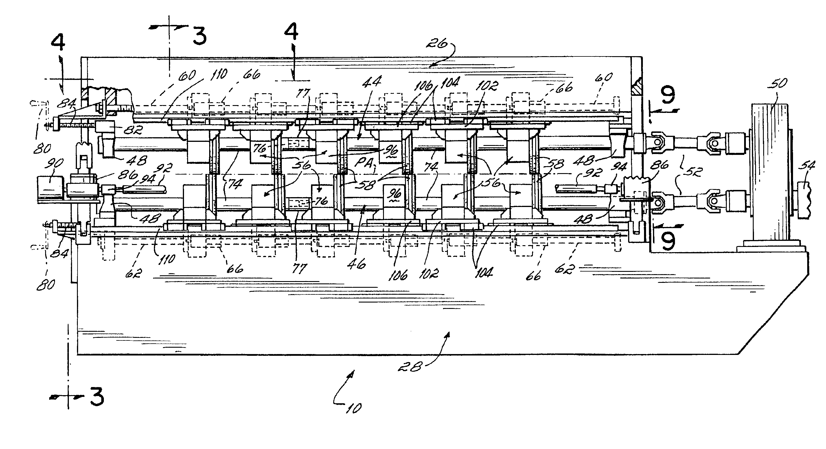
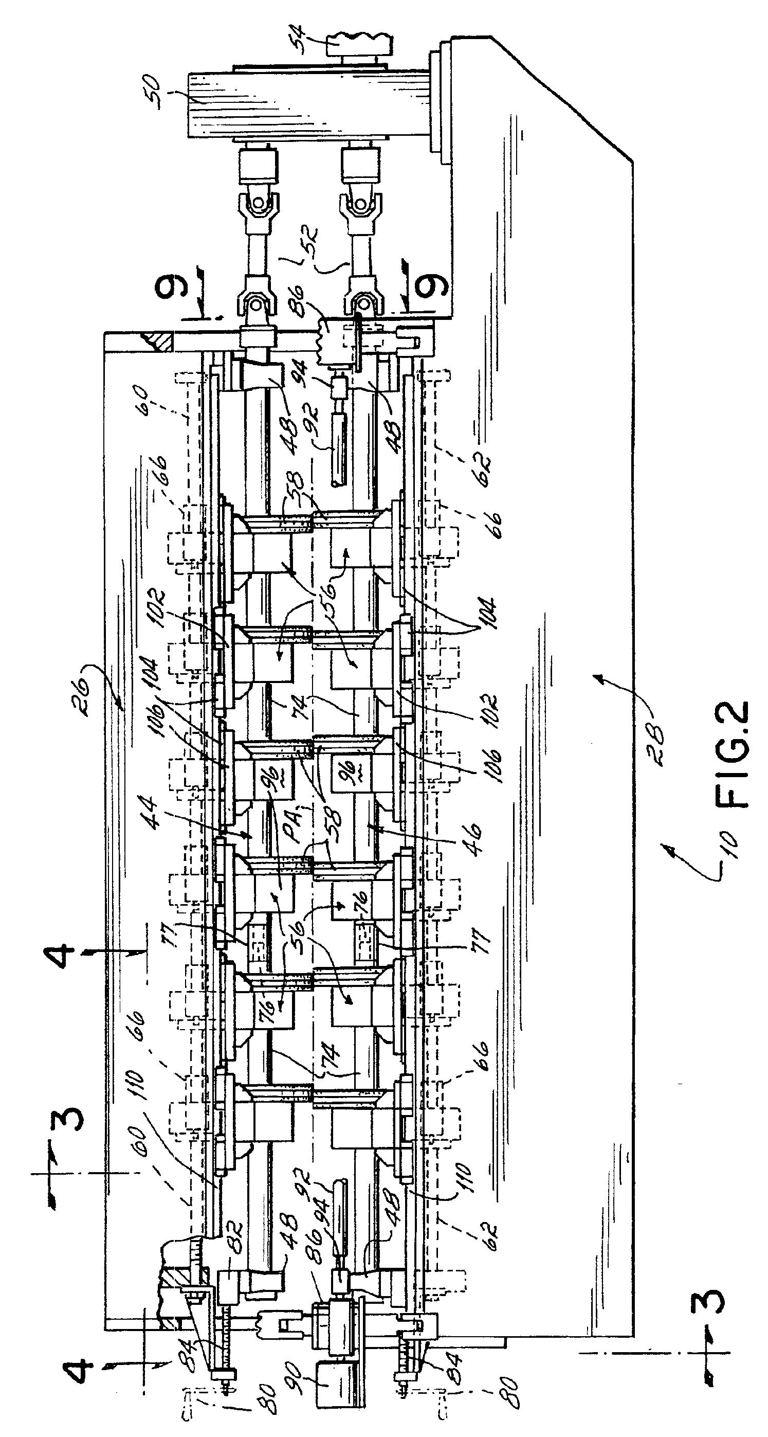
[0033]Referring to FIGS. 1 and 2, a presently preferred embodiment of the slitting machine 10 includes an upper frame 26 movably coupled at spaced ends thereof to a lower frame 28. The upper and lower frames 26, 28 of the machine 10 include upper and lower drive shaft assemblies...


PUM

PropertyMeasurementUnit
Thicknessaaaaaaaaaa

Abstract

A machine for slitting a metal sheet has a number of knife holder assemblies each containing a rotary knife. The knife holder assemblies are mounted for movement along upper and lower rotating shafts which rotate the knives during a slitting operation. The position of the knife holder assemblies is programmably controlled for efficient and accurate positioning and adjustment of the knives along the rotating shafts for a variety of slitting configurations. Additionally, each of the upper and lower drive shafts contains a pair of drive shaft sections that are normally connected together during operation and can be disconnected for servicing of the knife holder assemblies on the shafts. The slitting machine includes upper and lower frames that are movable relative to each other by adjustment of a pair of jack screws to slit metal sheets of differing thicknesses without labor intensive adjustment or reconfiguration of the machine.

Description

FIELD OF THE INVENTION[0001]The present invention relates generally to slitter machines for slitting sheet metal into “mults” or strips and, more particularly, to slitter machines having adjustable knives for varying the size and / or number of mults processed by the slitter machine.BACKGROUND OF THE INVENTION[0002]Much of the steel produced by mills is in the form of coiled steel sheet, but rarely does the sheet correspond in width to the multitude of products that are stamped or otherwise formed from it. Accordingly, the steel sheet is usually slit longitudinally to sizes suitable for the particular products. Indeed, special slitting machines are made for this purpose.[0003]The typical slitting machine has circular blades or knives arranged in pairs on two powered shafts or arbors, there being one knife of each pair on one of the arbors and the second knife of the pair on the other arbor. The arbors are connected to a drive system for counter-rotation. During operation, sheet metal ...

Claims


Application Information

Patent Timeline
IPC IPC(8): B26D1/14B23D19/06B23D35/00
CPCB23D35/004B23D35/007B26D2007/2664Y10T83/7876Y10T225/14Y10T83/538Y10T83/7847Y10T83/04Y10T83/7826Y10T83/7859Y10T83/659
Inventor FLAHERTY, PATRICK M.AHRNS, RICK L.RUTSCHILLING, CHARLES G.
Owner HERR VOSS STAMCO INC
Why Eureka
Try Eureka