Sealing device for a high-pressure sealing of line junctions

a sealing device and high-pressure technology, applied in the direction of hose connections, screw threaded joints, machines/engines, etc., can solve the problems of high cost of sealing devices used by known fuel injectors, sealing problems between individual components, so as to prevent damage to the cutting edge, reduce cost, and reduce manufacturing costs

Inactive Publication Date: 2006-11-14
CONTINENTAL AUTOMOTIVE GMBH
View PDF18 Cites 2 Cited by
  • Summary
  • Abstract
  • Description
  • Claims
  • Application Information

AI Technical Summary

Benefits of technology

[0005]The object of the present invention is therefore to provide a sealing device for a high-pressure sealing of line junctions, especially with fuel injection systems which with a simple structure and simple, low cost manufacturing can prevent damage to the cutting edge, so that a safe seal is always guaranteed.
[0009]The inventive sealing device for a high-pressure sealing of line junctions comprises a cutting edge as well as a protective edge. The cutting edge serves to create a seal by means of plastic deformation, with both the cutting edge and also the component against the cutting edge being able to be plastically deformed. The protective edge runs essentially in parallel to the cutting edge and projects in the axial direction of the line over the cutting edge. The projecting protective edge thus provides protection for the cutting edge, since when parts knock together the protective edge is hit first and thus deforms instead of the cutting edge. This can prevent damage to the cutting edge occurring, and thus an improved sealing characteristic of the sealing device can be achieved In this case the protective edge is embodied in such a way that it can be easily deformed during installation of the component so that the actual sealing effect is always provided by the cutting edge of the sealing device. Since the protective edge projects in an axial direction over the cutting edge, the protective edge is deformed in an axial direction in such a way that the cutting edge comes into contact with the next component to make the seal. This means that in accordance with the invention an especially low-cost protection against damage can be provided amazingly simply for a cutting edge which makes a seal.
[0010]To make it possible for the protective edge to deform especially easily during assembly, a first indentation or cutout is preferably embodied between the cutting edge and the protective edge.
[0011]To allow an even better slight deformability of the protective edge, a second cutout is embodied in the side of the protective edge facing away from the cutting edge. This produces a neck-shaped constriction between the protective edge and the component, so that a protective edge which is easily deformable using only slight force is provided.
[0012]In an especially preferred embodiment the cutouts have a U-shaped cross section, so that no abrupt transitions arise between the cutting edge and the protective edge. This ensures a secure deformation of the protective edge during assembly, to release the cutting edge without the protective edge being able to break off for example and an unwanted sharp broken edge being produced.

Problems solved by technology

Because of the very high pressures involved there are frequently sealing problems between individual components of the common rail system.
This is why expensive sealing devices have been used by known fuel injectors.
This cutting edge is however very sensitive to damage, such for example from components knocking into each other, such as can occur for example during assembly or during manufacturing, these are being transported as loose parts.

Method used


Image

  • Sealing device for a high-pressure sealing of line junctions
  • Sealing device for a high-pressure sealing of line junctions

Examples


Embodiment Construction

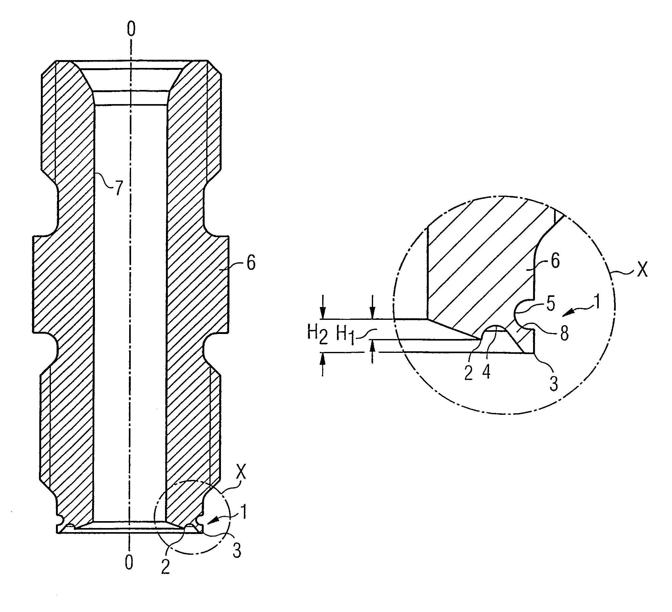
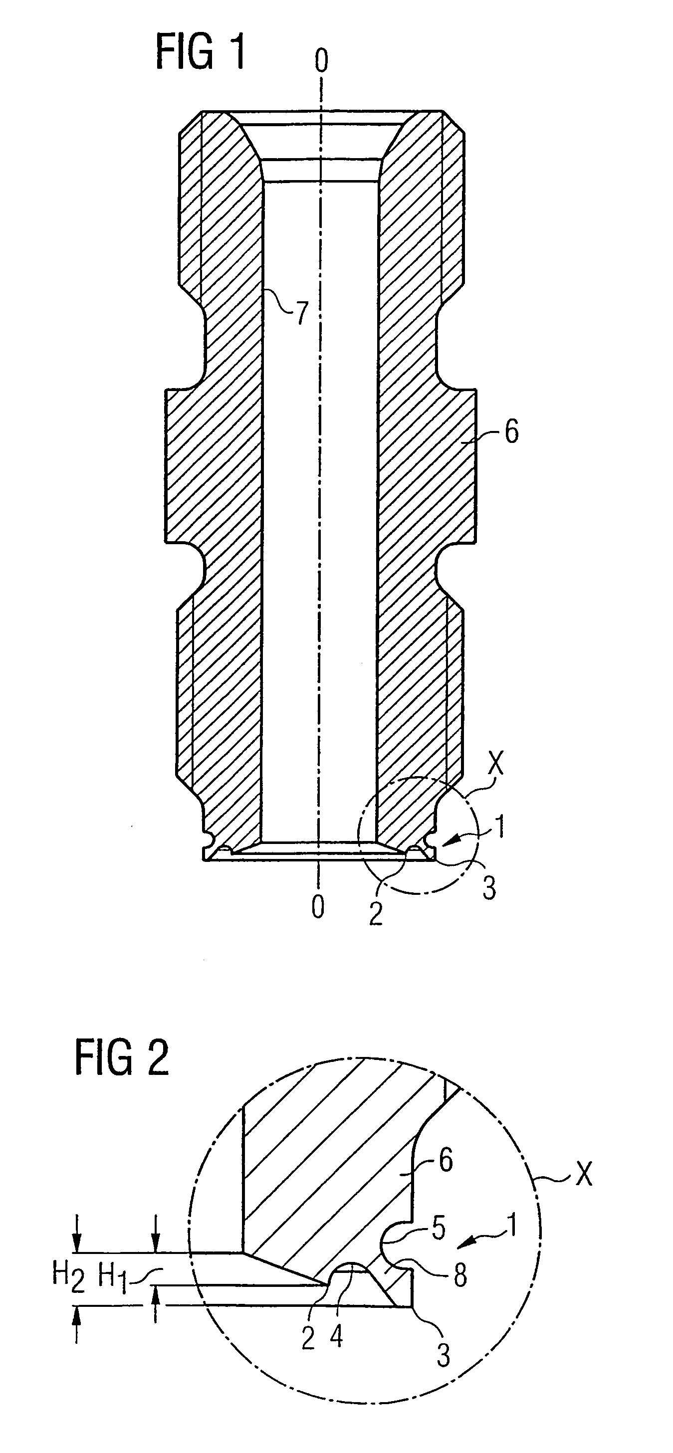
[0019]FIG. 1 shows a pressure pipe connector 6 which features an inventive sealing device 1 at one of its ends in axial direction 0-0. The pressure pipe connector 6 is used as an intermediate element between an injector of a fuel injection system and a high-pressure line. Fuel under high pressure is fed to the injector via this high-pressure line. The sealing device 1 is arranged at the end of the pressure pipe connection 6 which is attached to the injector.

[0020]The inventive sealing device 1 is shown in detail in FIG. 2. The sealing device 1 comprises a cutting edge 2 and a protective edge 3. The cutting edge 2 is arranged roughly in the middle of the wall thickness of the pressure pipe connector 6 and slopes inwards conically towards a high-pressure line 7 embodied in the pressure pipe connector 6. The protective edge 3 is arranged on the extreme outside edge of the pressure pipe connector 6. Between the cutting edge 2 and the protective edge 3 is a first cutout 4 embodied in the...


PUM


Abstract

A sealing device (1) for a high-pressure sealing of line junctions comprises a cutting edge (2) and a protective edge (3). The cutting edge (2) permits a sealing of the line junction by means of plastic deformation. The protective edge (3) extends essentially parallel to the cutting edge (2) and projects beyond the cutting edge (2) in an axial direction 0-0 of the line.

Description

CROSS REFERENCE TO RELATED APPLICATION[0001]This application is a continuation of International Application No. PCT / DE03 / 01165 filed Apr. 9, 2003 which designates the United States, and claims priority to German application no. 102 16 280.8 filed Apr. 12, 2002.TECHNICAL FIELD OF THE INVENTION[0002]The present invention relates to a sealing device for a high-pressure sealing of line junctions in fuel injectors.DESCRIPTION OF THE RELATED ART[0003]Fuel injectors are used for example in common rail injection systems to inject fuel under high pressure into the combustion chamber, which is fed to the injector via a high-pressure line from a storage tank. Because of the very high pressures involved there are frequently sealing problems between individual components of the common rail system. These types of sealing problems should however be avoided in any event, in order to meet environmental requirements on the one hand and on the other hand to prevent escaping fuel catching fire on hot p...

Claims


Application Information

Patent Timeline
Patent Type & Authority Patents(United States)
IPC IPC(8): F16L13/14F02M55/00F02M55/02F16J15/06F16L15/04
CPCF02M55/005F02M55/02F16L15/009
Inventor NEUMAIER, MARTIN
Owner CONTINENTAL AUTOMOTIVE GMBH
Why Eureka
Try Eureka