Printed board machining apparatus

a printing board and machining technology, applied in the direction of manufacturing tools, transportation and packaging, large fixed members, etc., can solve the problems of large amount of compressed air to support the pressure foot, unstable pressurization of the stiffening plate, and large fluctuation of the pressurizing force, so as to improve the machining efficiency without dropping the machining accuracy

Active Publication Date: 2006-11-14
HITACHI SEIKO LTD
View PDF13 Cites 21 Cited by
  • Summary
  • Abstract
  • Description
  • Claims
  • Application Information

AI Technical Summary

Benefits of technology

[0016]It is an object of the invention to provide a printed board machining apparatus whose machining efficiency is improved without dropping its machining accuracy.
[0022]Preferably, the printed board machining apparatus is provided with a pressure sensor for measuring a negative force within the space so that the compressed gas supplying means can increase or decrease the pressure of the compressed gas in accordance with the decrease or increase of the pressure measured by the pressure sensor.
[0023]As described above, according to the invention, the pressure of the compressed gas blown out of the compressed gas blowout port is set at the pressure which will not interfere with the contact face of the pressure foot contacting the workpiece, so that it is possible to prevent the stiffening plate from being lifted up with a small amount of gas and to improve machining speed and accuracy.

Problems solved by technology

However, the prior art printed board hole driller has required a large amount of compressed air to support the pressure foot.
Further, the pressurizing force fluctuates considerably, and the pressurization of the stiffening plate and the printed boards has been unstable as compared to the case of abutting the pressure foot directly to the stiffening plate.

Method used


Image

  • Printed board machining apparatus
  • Printed board machining apparatus
  • Printed board machining apparatus

Examples


Embodiment Construction

[0030]A printed board hole driller, i.e., an exemplary printed board machining apparatus, of a preferred embodiment of the invention will be explained below with reference to the drawings.

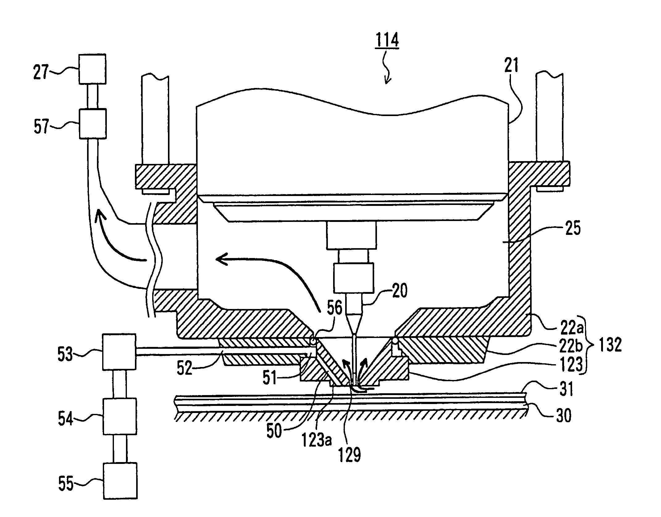
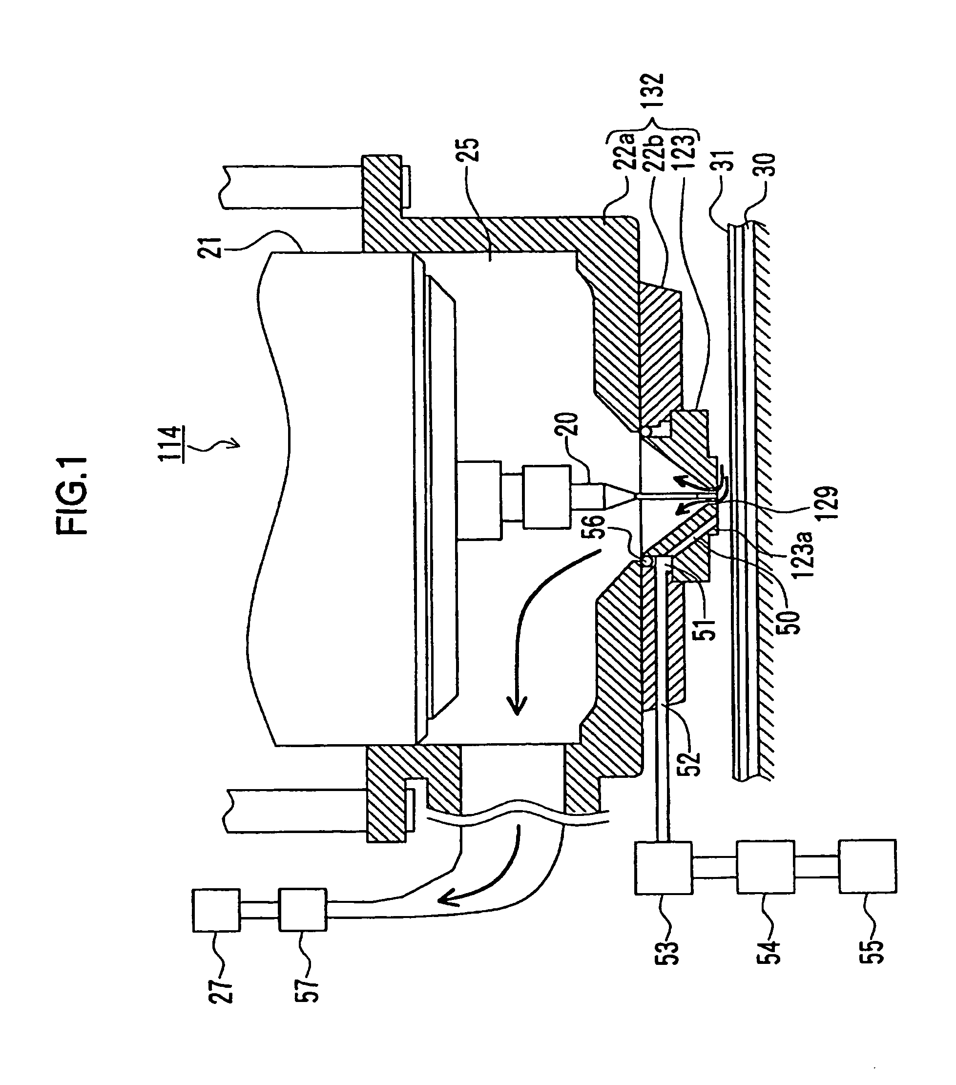
[0031]FIG. 1 is a front section view of an edge part of a spindle and a pressure foot of the inventive printed board hole driller.

[0032]It is noted that in the following description, the same reference numerals as those in the prior art described above denote the same or corresponding parts, and an explanation thereof concerning the structure and operation thereof will be omitted below.

[0033]A pressure foot 132 is composed of a body portion 22a, an adapter 22b formed hermetically in a body with the body portion 22a, and a bush 123. The housing 10 supports the body portion 22a through a cylinder (not shown) so that it fits coaxially with a spindle 21 and moves up and down in the Z-axis direction. Thus, the pressure foot 132 fits with the spindle 21 so as to be movable along the axial direction of th...


PUM

PropertyMeasurementUnit
thicknessaaaaaaaaaa
pressureaaaaaaaaaa
vacuumaaaaaaaaaa

Abstract

There is provided a printed board machining apparatus that is capable of improving machining efficiency without hampering machining accuracy. The printed board machining apparatus includes a pressure foot which is provided with a port whose one end is opened at a lower surface of the pressure foot facing a stiffening plate, and whose other end is connected to a compressed gas source to blow out gas from the port at a pressure which does not interfere with the pressure foot pressurizing the stiffening plate and printed boards in machining the printed boards. It is noted that the gas is blown out during a period of time at least when the pressure foot and the stiffening plate are moving relatively in the horizontal direction.

Description

BACKGROUND OF THE INVENTION[0001]1. Field of the Invention[0002]The present invention relates to a printed board machining apparatus for machining workpieces by a tool while pressing down the peripheral part of the workpiece to a table by a pressure foot.[0003]2. Related Background Art[0004]FIG. 4 is a schematic perspective view showing an outside view of a prior art printed board hole driller, i.e., an exemplary printed board machining apparatus, and FIG. 5 is a front section view of an edge of a spindle and a pressure foot of the printed board hole driller shown in FIG. 4.[0005]As shown in FIGS. 4 and 5, the printed board hole driller 14 is constructed so that a table 1 therein moves in the direction of an arrow X by an X-axis motor 2 on a track 4 fixed on a bed 3. A column 5 is fixed to the bed 3 so as to straddle the table 1. A cross slide 6 is arranged to move in the direction of an arrow Y on a track 9 fixed on the column 5 by a Y-axis motor 7 and a ball screw 8. A housing 10 ...

Claims


Application Information

Patent Timeline
Patent Type & Authority Patents(United States)
IPC IPC(8): B23B47/00B23Q11/00B23B41/00B23B47/28H05K3/00
CPCB23Q11/0046H05K3/0047Y10T408/44Y10T408/21Y10T409/304088Y10T408/50Y10T409/304032B23B47/00B23B47/28
Inventor KADO, HIROFUMIITO, YASUSHISUZUKI, NOBUHIKO
Owner HITACHI SEIKO LTD
Why Eureka
Try Eureka