Electrospinning of fibers using a rotatable spray head

a technology of fibers and spray heads, applied in the field of fiber electropinning, can solve the problems of large-scale nanofiber production including solvent volatilization in small spaces, background techniques using a multiplicity of individually electrified needles and/or a multiplicity of solution reservoirs are not conducive to large-scale manufacturing, and the extrusion of fibers is twisted and contorted

Active Publication Date: 2006-11-14
RES TRIANGLE INST
View PDF88 Cites 107 Cited by
  • Summary
  • Abstract
  • Description
  • Claims
  • Application Information

AI Technical Summary

Problems solved by technology

U.S. Patent Application Publication No. U.S. 2002 / 0100725 A1 describes, besides the solvents and substances used for nanofibers, the difficulties of large scale production of the nanofibers including the volatilization of solvents in small spaces.
Hence, the background techniques using a multiplicity of individually electrified needles and / or a multiplicity of solution reservoirs are not conducive to large scale manufacturing.
However, the emission of fibers from a face surface of a rotating spray head results in twisting and contorting of the extruded fibers due to the centripetal forces existing between the free end of the fiber and the end still attached to the extruding medium.

Method used


Image

  • Electrospinning of fibers using a rotatable spray head
  • Electrospinning of fibers using a rotatable spray head
  • Electrospinning of fibers using a rotatable spray head

Examples


Embodiment Construction

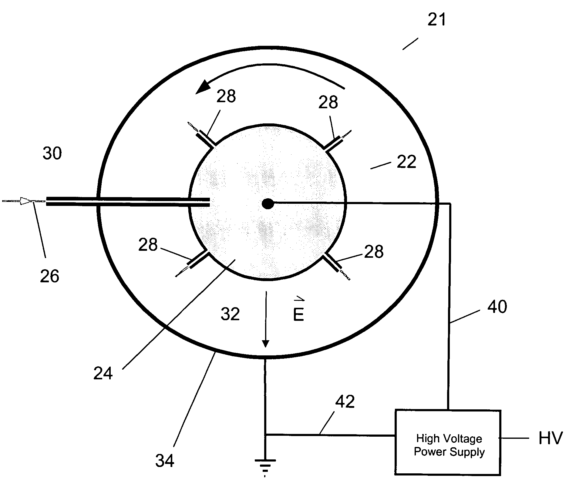
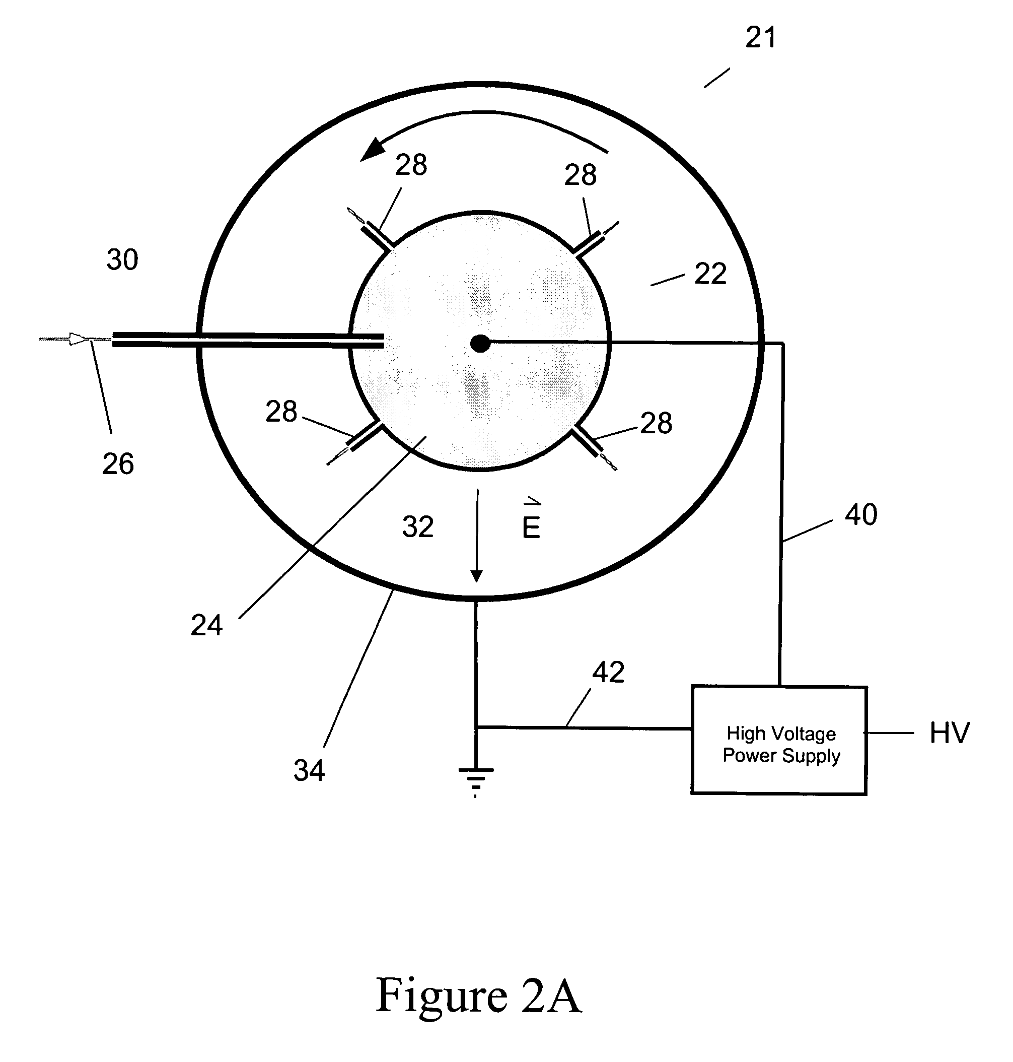
[0032]Referring now to the drawings, wherein like reference numerals designate identical, or corresponding parts throughout the several views, and more particularly to FIG. 2A, FIG. 2A is a schematic illustration showing a top view of an electrospinning apparatus 21 of one embodiment of the present invention in which a rotatable spray head 22 including a reservoir 24 holding a substance from which the fibers are to be extruded. FIG. 2B shows a side view of the electrospinning apparatus 21. In FIG. 2B, the electrospray medium is shown illustratively being feed to the reservoir 24 along an axial direction of the electrospinning apparatus 21. The electrospray medium 26 is electrospun from a plurality of extrusion (or electrospinning) elements 28 extending as shown in FIGS. 2A and 2B from the peripheral wall of the reservoir 24. The rotatable spray head 22 is preferably rotated about its center, and the spray of the electrospray medium 26 occurs radially from the extrusion elements 28 p...


PUM

PropertyMeasurementUnit
interior cross sectional areaaaaaaaaaaa
electric field strengthaaaaaaaaaa
diametersaaaaaaaaaa

Abstract

Apparatus and method for electrospinning fibers in which the apparatus includes a spray head having a longitudinal axis and including at least one electrospinning element disposed in a peripheral wall of the spray head surrounding the longitudinal axis. The electrospinning element includes a passage by which a substance from which the fibers are to be electrospun is provided to a tip of the extrusion electrospinning element. The electrospinning element extends from the peripheral wall in a direction from the longitudinal axis and is configured to electrospin the fibers by electric field extraction of the substance from the tip of the extrusion electrospinning element. Accordingly, the method includes providing a substance from which the fibers are to be composed to a tip of an electrospinning element in a peripheral wall of a spray head having a longitudinal axis, rotating the spray head or a collector configured to receive the fibers around the longitudinal axis, applying in a direction from the longitudinal axis of the spray head an electric field to the tip of the electrospinning element to electrospin by electric field extraction the substance from the tip of the electrospinning element to form the fibers, and collecting the fibers on the collector.

Description

CROSS REFERENCE TO RELATED APPLICATIONS[0001]This application is related to U.S. application Ser. No. 10 / 819,942, filed on Apr. 8, 2004, entitled “Electrospray / Electrospinning Apparatus and Method,” the entire contents of which are incorporated herein by reference. This application is related to U.S. application Ser. No. 10 / 819,945, filed Apr. 8, 2004, entitled “Electrospinning in a Controlled Gaseous Environment,” the entire contents of which are incorporated herein by reference.DISCUSSION OF THE BACKGROUND[0002]1. Field of the Invention[0003]This invention relates to the field of electrospinning of fibers from polymer solutions.[0004]2. Background of the Invention[0005]Nanofibers are useful in a variety of fields from clothing industry to military applications. For example, in the biosubstance field, there is a strong interest in developing structures based on nanofibers that provide a scaffolding for tissue growth effectively supporting living cells. In the textile field, there i...

Claims


Application Information

Patent Timeline
Patent Type & Authority Patents(United States)
IPC IPC(8): B32B27/12D01D5/00D01D5/18D01H7/00
CPCB82Y30/00D01D5/0069D01D5/18D04H1/4242D04H1/728D04H3/002D04H3/016Y10T442/614
Inventor ANDRADY, ANTHONY L.ENSOR, DAVID S.NEWSOME, RANDALL J.
Owner RES TRIANGLE INST
Why Eureka
Try Eureka