Nits separator

a technology of nit separator and nit filter, which is applied in the field of nit separator, can solve the problems of uneconomical processing of this known plant, poor quality of the resulting product from a plant according to wo 8703626 a1, and inability to obtain a product essential free of ni

Inactive Publication Date: 2006-11-14
OERLIKON TEXTILE GMBH & CO KG
View PDF13 Cites 6 Cited by
  • Summary
  • Abstract
  • Description
  • Claims
  • Application Information

AI Technical Summary

Benefits of technology

[0031]As the separated nits account only for a minor part of the fibrous material sucked away from the forming head, the advantages achieved by using a plant of the kind described in accordance with the invention can partly be maintained even if the separated nits are transported directly to the defibrato

Problems solved by technology

Also, the process of this known plant is uneconomical because the large quantities of energy, which need to be used for driving the main current through the large screen for only separating the few percent of nits in the main current.
The quality of the resulting product from a plant according to WO 8703626 A1 also will be poor as the nits in this plant are separated from a large current having a low percent of nits, as in D1.
Moreover, it is not possible to obtain a product whic

Method used


Image

  • Nits separator
  • Nits separator

Examples


Embodiment Construction

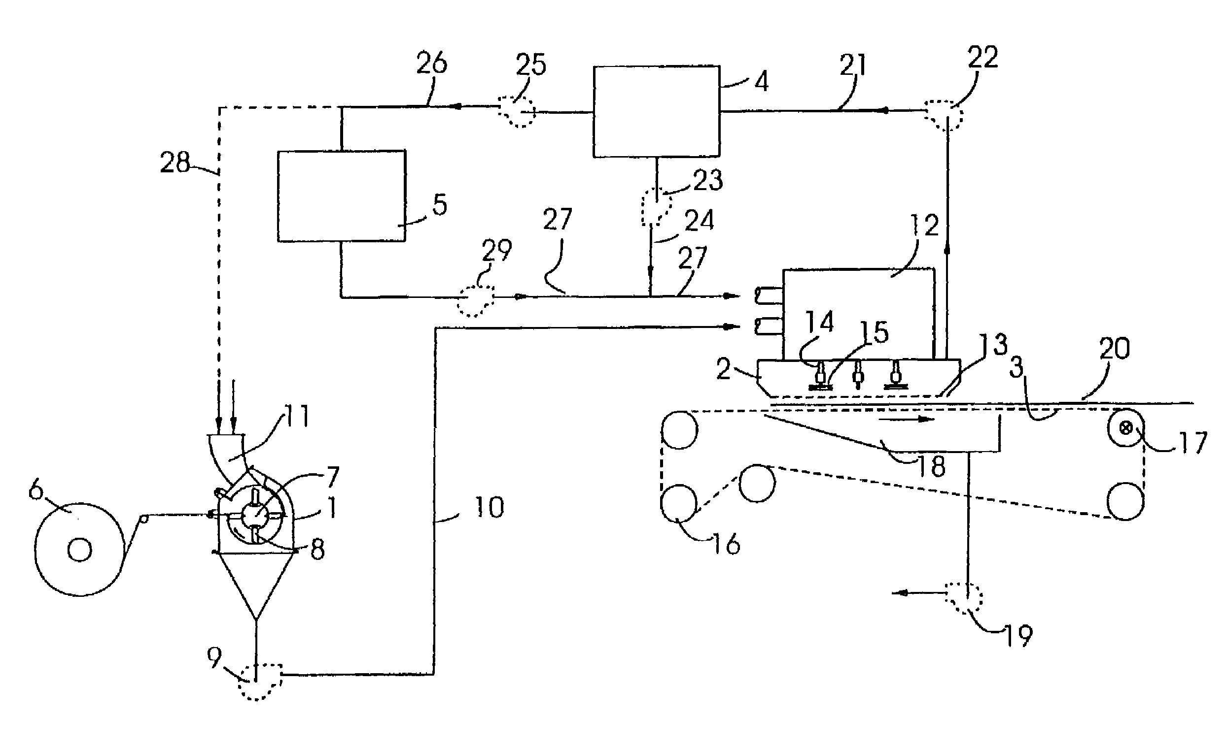
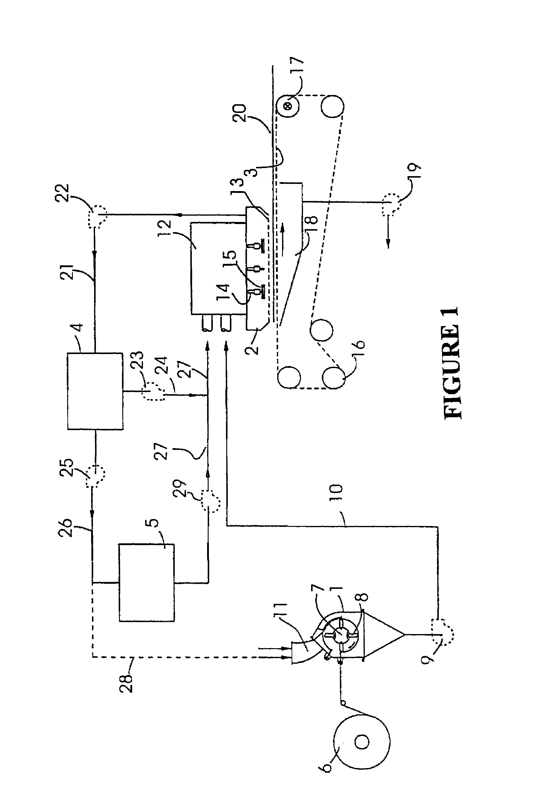
[0036]The plant includes a number of transport fans. These are drawn with dotted lines to indicate that one or several of these transport fans may be omitted in special variations of the construction shown.

[0037]The main components of the plant in the case shown in FIG. 1 are a known hammer mill 1, an existing forming head 2, and existing forming wire 3, which is mounted underneath the forming head, a nits separator 4 and a nits-opener 5.

[0038]Fibre material, which in this example is assumed to be cellulose pulp, is fed to the hammer mill 1 on a roller 6. The pulp is, in a known way, defibrated into single fibres in the hammer mill by means of a rotor 7, which has hinged swingles 8 and is rotating during operation.

[0039]By means of a first transport fan 9 and via a first duct 10, the fibres are channelled to the forming head 2 on an air stream, which is formed as the hammer mill, in the direction of the arrow, is supplied with air via an air intake 11.

[0040]The forming head 2 shown ...


PUM

PropertyMeasurementUnit
Energyaaaaaaaaaa

Abstract

A plant which serves to produce a nonwoven web of fibers out of a fibrous material, such a cellulose pulp. The plant comprises a hammer mill for defibrating the fibrous material and a forming head for forming a web of fibers on an endless forming wire, which, during operation, runs mainly horizontally, a first transport fan for transporting defibrated fiber to the forming head via a first air duct and a second transport fan to extract nits from the forming head via a second air duct. Furthermore, the plant comprises a separator, which is connected to the second air duct and arranged for separating the nits and the well-opened fiber, a third transport fan for returning the separated, well-opened fibers to the forming head, and a nits-opener for converting the separated nits into well-opened fiber. The separated nits are transported from the nits separator to the nits-opener by means of a fourth transport fan via a fourth air duct. The defibrated fibers are returned to the forming head by means of a fifth transport fan via a fifth air duct. The plant is easy to control and is capable of producing optimally high quality fiber products. In addition, the plant allows the defibrator to defibrate new fiber material at full capacity so that the remainder of the plant is able to produce at an optimum output level. The plant is furthermore very energy-saving.

Description

FIELD OF THE INVENTION[0001]The invention relates to a plant for producing a nonwoven fibre web out of a fibrous material and which comprises a defibrator, such as a hammer mill, for forming the fibre web on a endless forming wire which, when in operation, mostly runs horizontally, a first transport fan which transports defibrated fibres via a first duct to a forming head, and a second transport fan which extracts nits from the forming head.[0002]Nits are knots, which occur in the defibrated fibrous material as a result either of incomplete defibration in the defibrator, during transport to the forming head or during the processes which take place within the forming head.[0003]Nits impair the quality of the finished fibre product. Conventionally, the nits are removed by extracting them from strategic locations within the forming head and returning the extracted material to the hammer mill where the nits are opened to singular fibres and then returned to the forming head.[0004]Achiev...

Claims


Application Information

Patent Timeline
IPC IPC(8): B27N3/04D21B1/06D04H1/72D21D1/32D21F9/00
CPCD21B1/06D21D1/32D21F9/00
Inventor SORENSEN, BIRGER ELMGAARD
Owner OERLIKON TEXTILE GMBH & CO KG
Why Eureka
Try Eureka