Connector with a moving plate

a technology of connecting plate and moving plate, applied in the direction of coupling device connection, coupling parts engagement/disengagement, incorrect coupling prevention, etc., to achieve the effect of well-balanced locking

Active Publication Date: 2006-11-14
SUMITOMO WIRING SYST LTD
View PDF12 Cites 25 Cited by
  • Summary
  • Abstract
  • Description
  • Claims
  • Application Information

AI Technical Summary

Benefits of technology

[0009]A retaining force of the latch can be made stronger than the retaining force of the above-described semi-locking construction. Thus, an inadvertent movement of the moving plate from the first position to the second position can be prevented.
[0010]The receiving portion preferably is provided in the intermediate part of the mating surface of the moving plate to achieve well-balanced locking between the receiving portion and the latch. Thus, there is no need for plural receiving portions at the peripheral edge of the moving plate.
[0011]The latch is released from the receiving portion merely by inserting the second housing into the receptacle. Thus, a latched state by the latch and the receiving portion can be released easily.
[0016]The at least one auxiliary receiving portion preferably is at the inner peripheral surface of the receptacle, and the at least one auxiliary latch preferably is at a peripheral edge of the moving plate for resiliently engaging the auxiliary receiving portion with the latch disengaged from the receiving portion. Thus, inadvertent movement of the moving plate to the released position can be securely prevented.

Problems solved by technology

However, the semi-locking construction creates the possibility that the moving plate will disengage inadvertently from the projections, thereby freeing the leading ends of the tabs before the housings are connected.

Method used


Image

  • Connector with a moving plate
  • Connector with a moving plate
  • Connector with a moving plate

Examples


Embodiment Construction

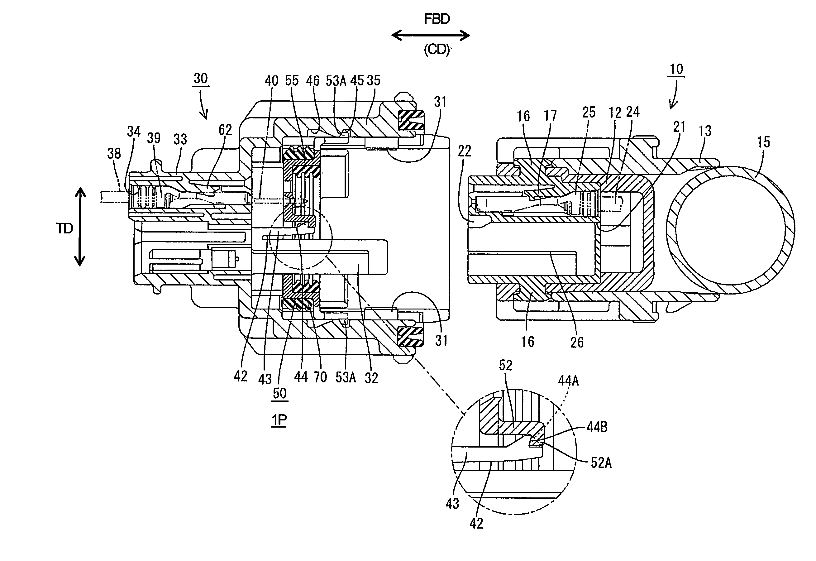
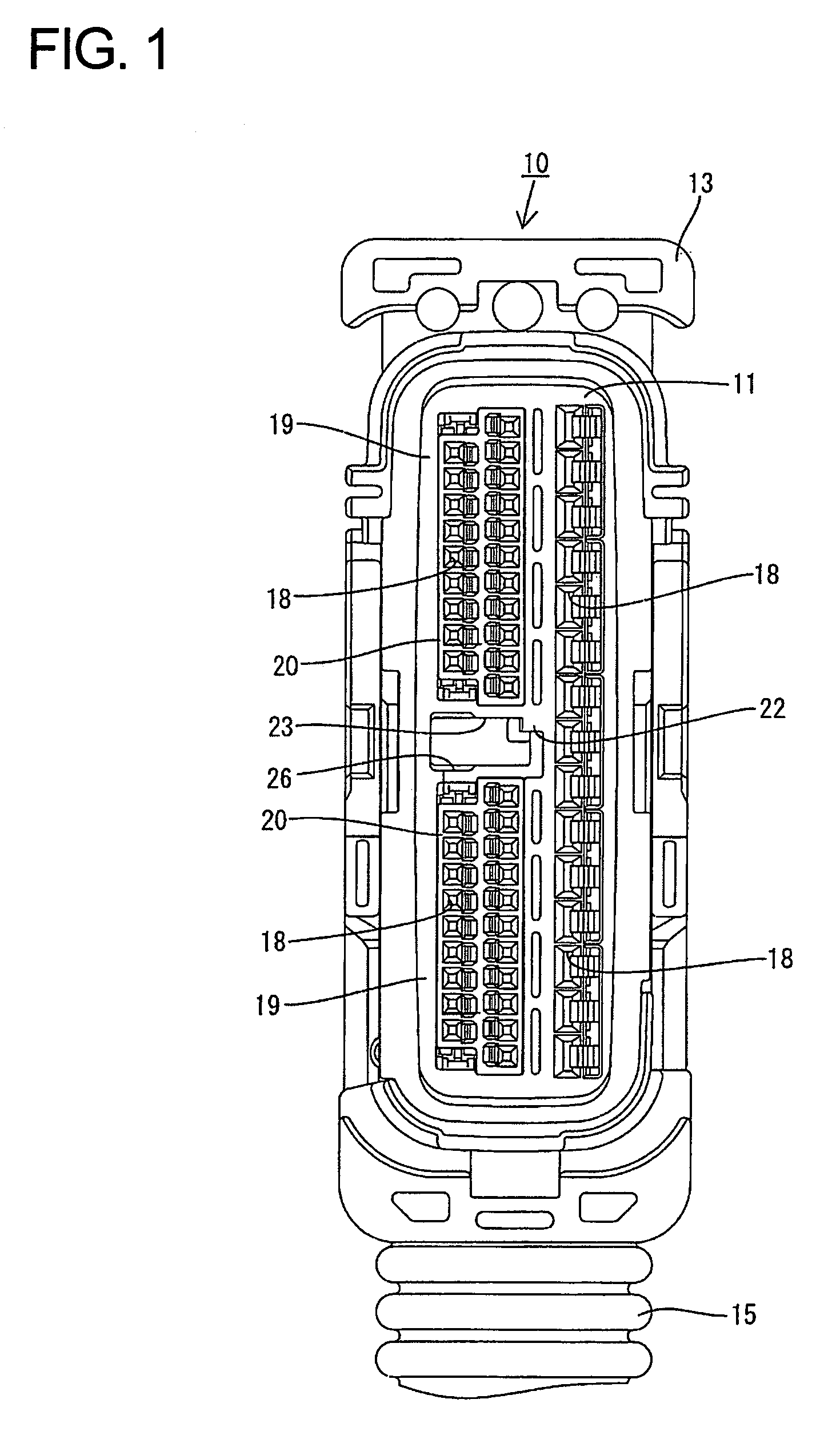
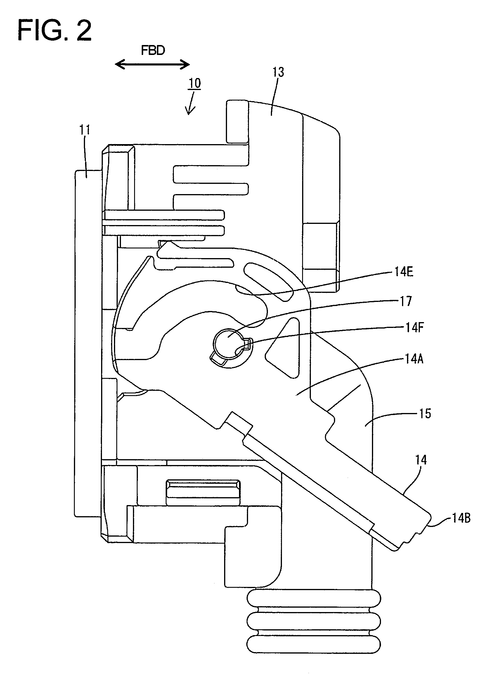
[0033]A connector according to the invention is illustrated in FIGS. 1 to 11 and has a female housing 10 and a male housing 30 connectable with each other along a connecting direction CD. In the following description, ends of the housings 10, 30 to be connected with each other are referred to as the front concerning forward and backward directions FBD, and reference is made to FIG. 1 concerning a vertical direction VD that is substantially normal to the forward and backward directions FBD.

[0034]The female housing 10 has a resin main body 11 that is long and narrow in a vertical direction VD. A resilient rubber grommet 12 is mounted from behind to cover substantially all of the main body 11 except the front surface and a resin grommet cover 13 is mounted on the outer side of the grommet 12. A lever 14 is mounted on the outer side of the grommet cover 13 and is operable to assist the connection of the two housings 10, 30.

[0035]The grommet 12 has a downward-projecting wire draw-out por...


PUM


Abstract

A moving plate (50) is movable between a retained position and a released position in a receptacle (35) of a male housing (30). One receiving portion (52) is provided in a middle part of the front surface of the moving plate (50), and a resiliently deformable latch (42) projects from the back surface of the receptacle (35) so that the leading end of the latch (42) is engageable with the receiving portion (52) through an insertion hole (64) of the moving plate (50). Movement of the moving plate (50) from the retained position to the released position is prevented by the resilient engagement of the latch (42) and the receiving portion (52). At the start of the connection of two housings (10, 30), a releasing portion (22) on the front surface of a female housing (10) contacts the latch (42) to disengage the latch (42) from the receiving portion (52).

Description

BACKGROUND OF THE INVENTION[0001]1. Field of the Invention[0002]The invention relates to a connector with a moving plate.[0003]2. Description of the Related Art[0004]Japanese Examined Utility Model Publication No. H05-12953 discloses a connector with a male housing that has a receptacle and a moving plate that can move forward and back in the receptacle. The connector also has male terminal fittings with tabs that project forward into the receptacle. Front ends of the tabs are in positioning holes of the moving plate when the moving plate is retained near the open front end of the receptacle. Thus, the front ends of the tabs are positioned vertically and transversely by the moving plate. A female housing pushes the moving plate back towards the rear of the receptacle in the process of fitting the female housing into the receptacle to start the connection of male and female terminal fittings.[0005]Projections on the inner peripheral surface of the receptacle and engage front and rear...

Claims


Application Information

Patent Timeline
Patent Type & Authority Patents(United States)
IPC IPC(8): H01R13/62H01R13/64
CPCH01R13/4538H01R13/62938
Inventor OKURA, YOSHIO
Owner SUMITOMO WIRING SYST LTD
Why Eureka
Try Eureka