

Exhaust gas purifying catalyst
a technology of exhaust gas and purifying catalyst, which is applied in the direction of physical/chemical process catalyst, metal/metal-oxide/metal-hydroxide catalyst, separation process, etc., can solve the problem of reducing the purifying performance of both rh and pt, the inability to sufficiently suppress the migration of rh from the upper catalyst layer to the lower catalyst layer, and the migration of rh on the upper catalyst layer tends to migrate. , to achieve the effect o
- Summary
- Abstract
- Description
- Claims
- Application Information
AI Technical Summary
Benefits of technology
Problems solved by technology
Method used
Image

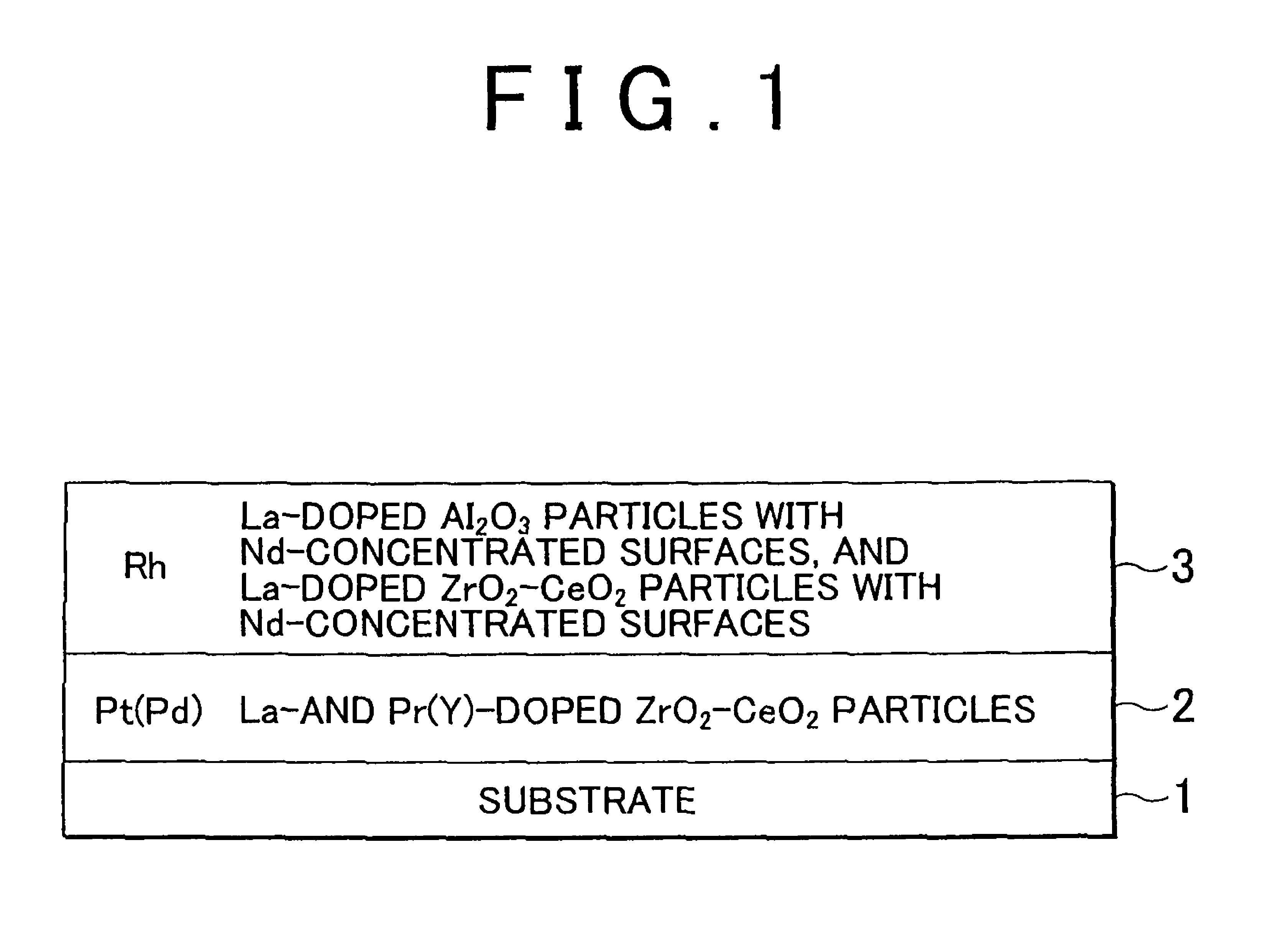
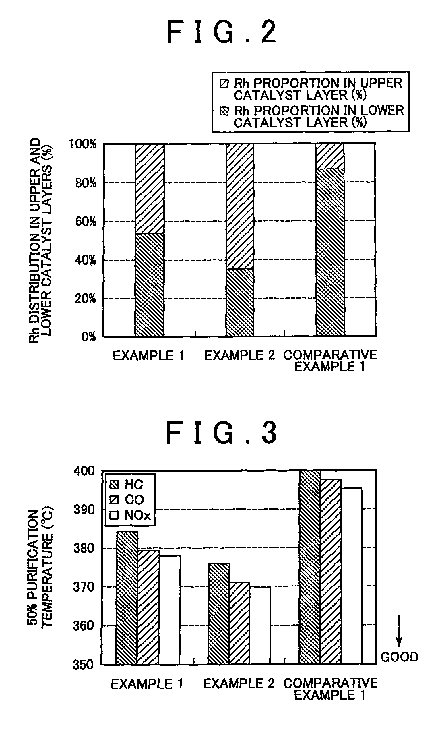
Examples
Embodiment Construction
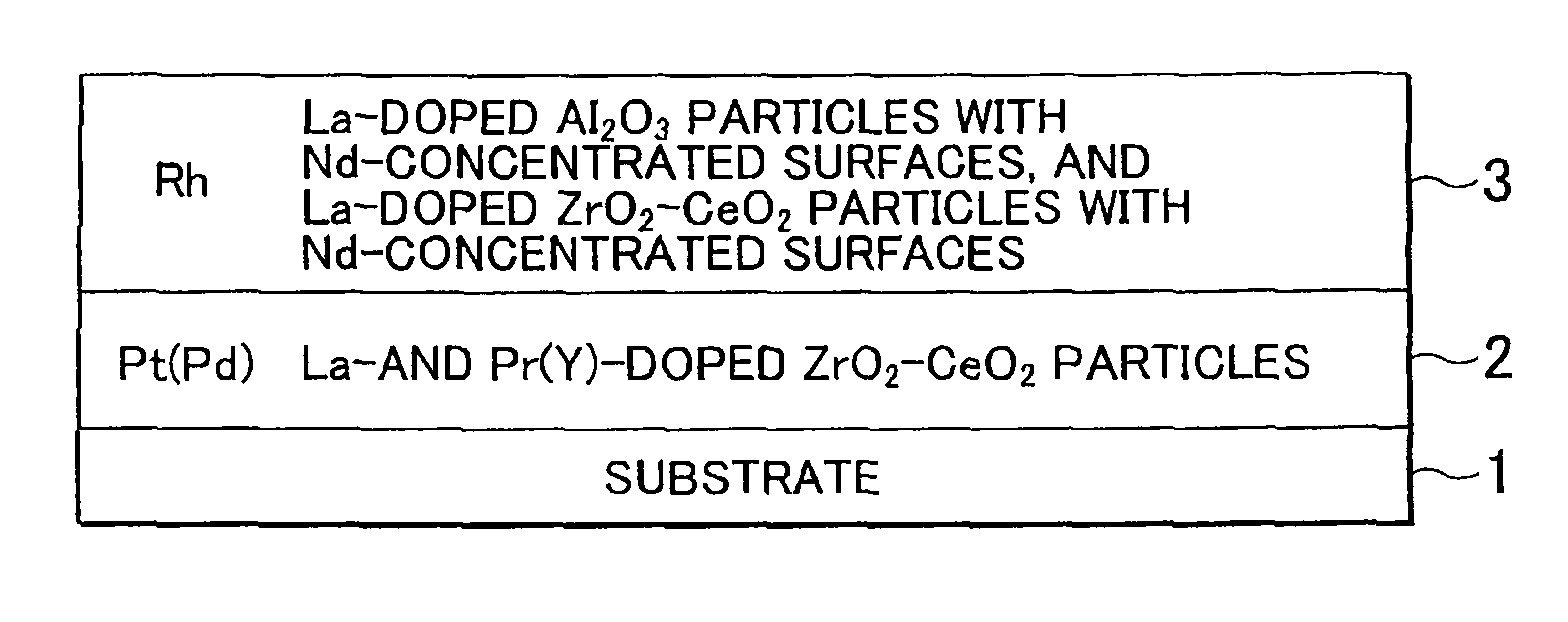
[0034]The exhaust gas purifying catalyst of the present invention has a substrate, a lower catalyst layer and an upper catalyst layer.
[0035]The substrate defines a gas passage and may be shaped into various forms such as a honeycomb shape, a foam shape or a plate shape. The material of which the substrate is formed is not particularly limited and may be a known material such as a ceramic, e.g. cordierite or SiC, or a metal.
[0036]The lower catalyst layer is formed on the surface of the substrate and has a lower catalytic precious metal and a lower-layer carrier on which the lower catalytic precious metal is supported.
[0037]The lower catalytic precious metal contains at least one of Pt and Pd. If desired, the lower catalytic precious metal may contain other precious metal catalysts such as Rh, as long as the performance of Pt and Pd is not adversely affected.
[0038]Preferably, the total concentration of Pt and Pd that are supported on the lower catalyst layer is 0.5 to 1.5 g per liter ...
PUM
| Property | Measurement | Unit |
|---|---|---|
| thickness | aaaaa | aaaaa |
| concentration | aaaaa | aaaaa |
| concentration | aaaaa | aaaaa |
Abstract
Description
Claims
Application Information