Permeable conductive shield having a laminated structure

a technology of conductive shields and laminated structures, which is applied in the direction of magnetic/electric field screening, electrical apparatus casings/cabinets/drawers, and semiconductor/solid-state device details. it can solve the problems of increasing the fabrication cost of enclosures, increasing the size and weight of enclosures, and building up heat in the components being shielded. , to achieve the effect of convenient manufacturing of laminated structures

Inactive Publication Date: 2006-11-14
IBM CORP
View PDF16 Cites 27 Cited by
  • Summary
  • Abstract
  • Description
  • Claims
  • Application Information

AI Technical Summary

Benefits of technology

[0008]It is, therefore, a principle object of this invention to provide a permeable conductive shield having an easily manufactured laminated structure.

Problems solved by technology

Another problem experienced with the commonly used types of EMI shields is the build up of heat in the components being shielded.
But this solution adds to the fabrication cost of the enclosure, increases its size and weight, and is certainly not an effective solution unless some sort of metallic, heat conducting, material is used.

Method used


Image

  • Permeable conductive shield having a laminated structure
  • Permeable conductive shield having a laminated structure
  • Permeable conductive shield having a laminated structure

Examples


Embodiment Construction

[0018]The invention will now be described in more detail by way of example with reference to the embodiments shown in the accompanying figures. It should be kept in mind that the following described embodiments are only presented by way of example and should not be construed as limiting the inventive concept to any particular physical configuration.

[0019]Further, if used and unless otherwise stated, the terms “upper,”“lower,”“front,”“back,”“over,”“under,” and similar such terms are not to be construed as limiting the invention to a particular orientation. Instead, these terms are used only on a relative basis.

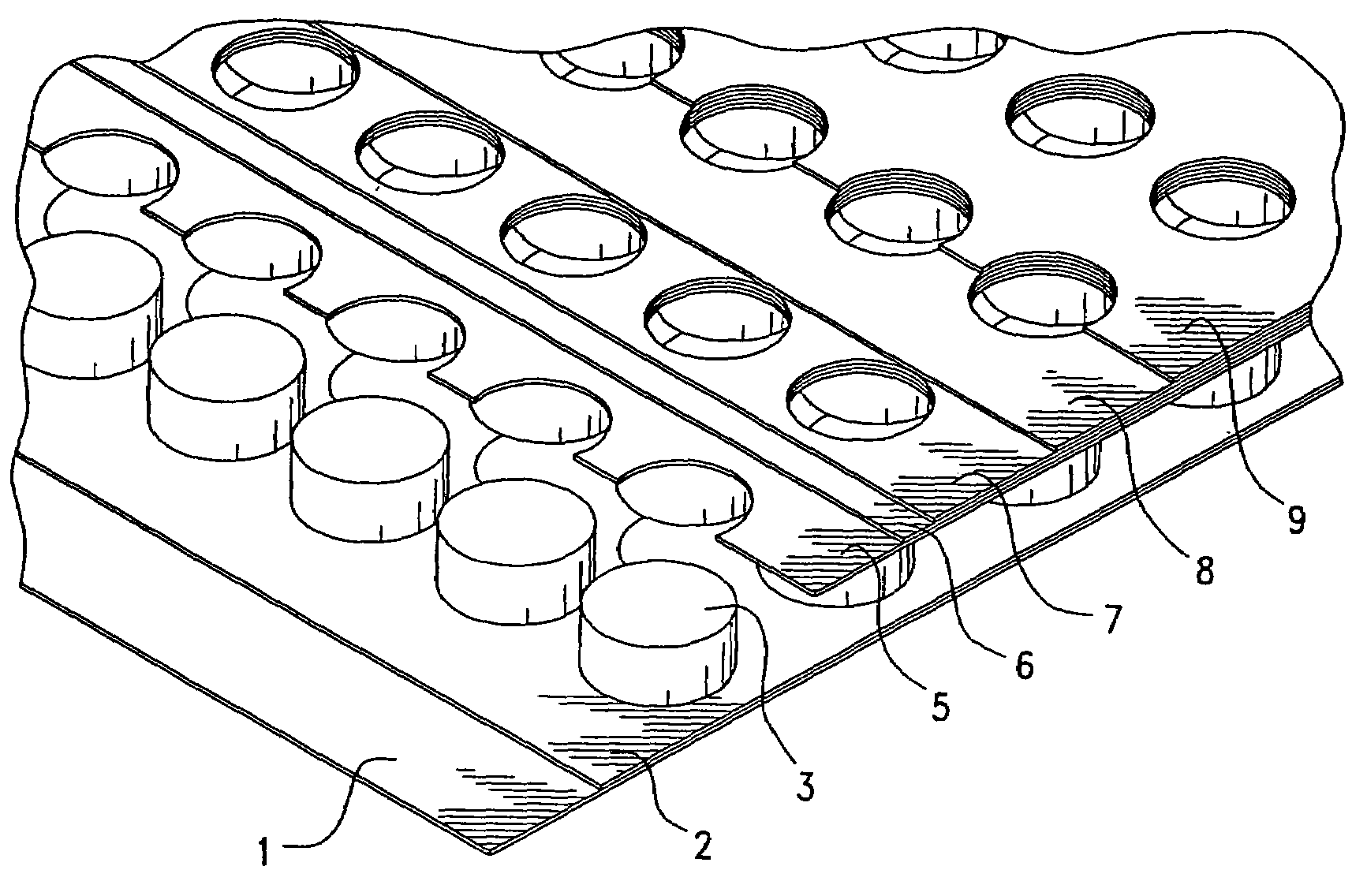
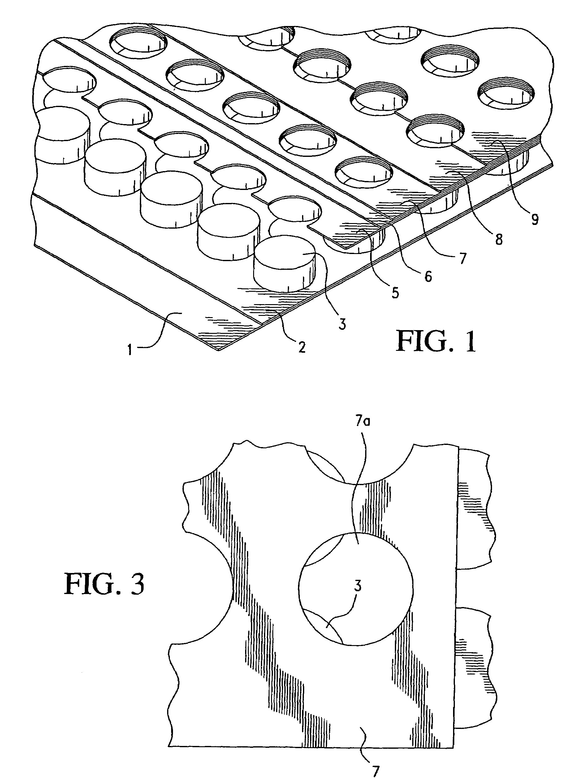
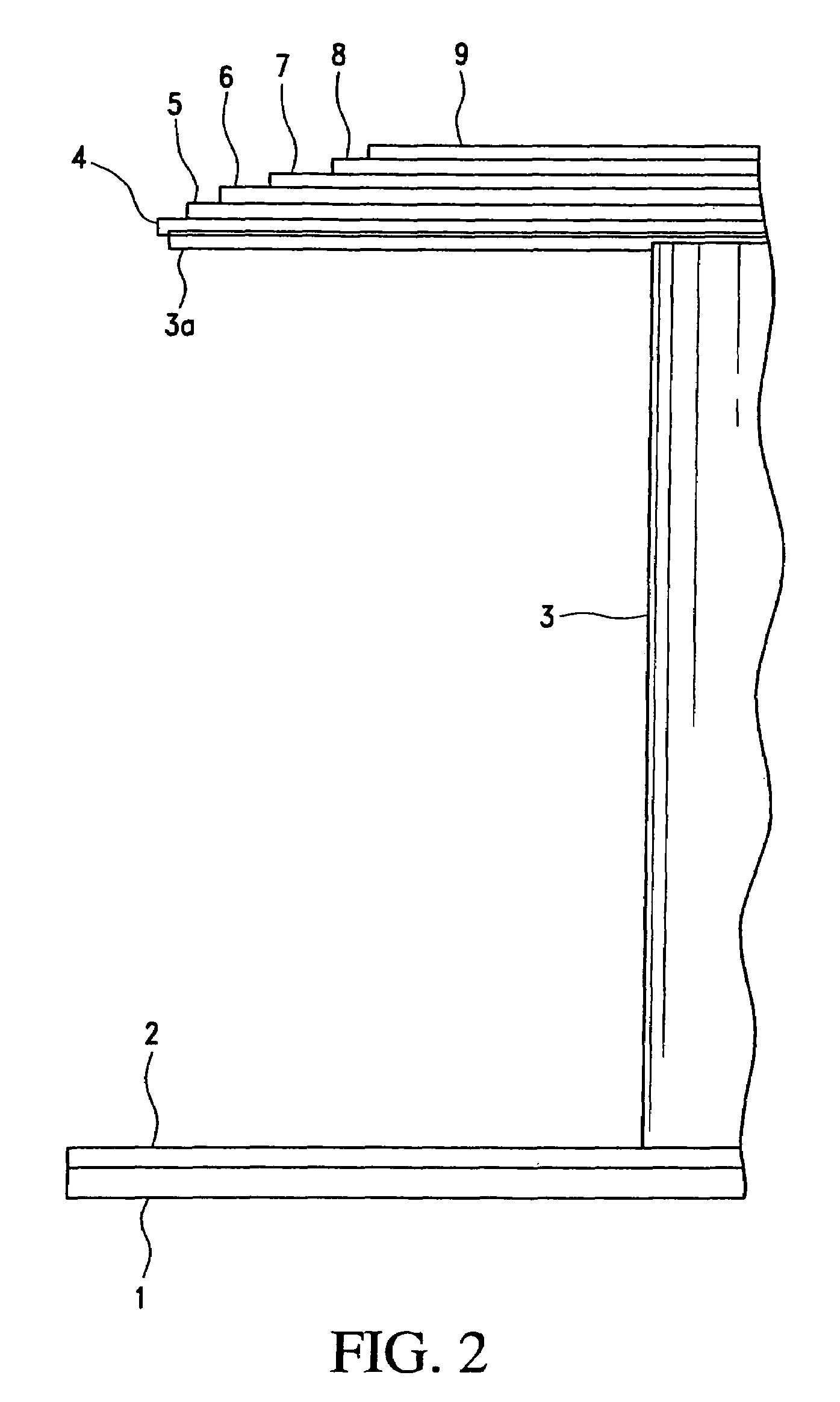
[0020]The present invention is directed toward a permeable conductive shield providing protection from electromagnetic interference and electrostatic discharge, and having a simple laminated structure suitable, for example, for application to the foil side or the component side of a printed circuit board.

[0021]FIG. 1 shows in a cut-away view a preferred embodiment of the invent...


PUM


Abstract

A permeable conductive shield providing protection from electromagnetic interference and electrostatic discharge has a laminated structure suitable for application to the foil side or the component side of a circuit board. The laminated structure includes an array of foam spacers arranged with spaces between them, a layer of foam attached to the top of the spacers, a first insulating sheet on the layer of foam spacers; a conductive sheet on the first insulating sheet, and a second insulating sheet on the conductive sheet. Each of the layers has a multiplicity of through holes aligned with corresponding through holes in the other layers and with the spaces between the foam spacers so as to allow airflow through the structure. The layers are bonded together with intervening adhesive layers. A pressure-sensitive adhesive is applied to the bottom of the spacers for attaching the permeable conductive shield to the circuit board.

Description

BACKGROUND OF THE INVENTION[0001]1. Field of the Invention[0002]The invention relates to a permeable conductive shield providing protection from electromagnetic interference and electrostatic discharge, and in particular, to such a permeable conductive shield having a simple laminated structure suitable for application to the foil side or the component side of a printed circuit board.[0003]2. Background Information[0004]The operation of electronic devices such as televisions, radios, computers, medical instruments, business machines, communications equipment, and the like is attended by the generation of electromagnetic radiation within the electronic circuitry of the equipment. Such radiation often develops as a field or as transients within the radiofrequency band of the electromagnetic spectrum, i.e., between about 10 kHz and 10 GHz, and is termed “electromagnetic interference” or “EMI” as it is known to interfere with the operation of other proximate electronic devices. To atten...

Claims


Application Information

Patent Timeline
Patent Type & Authority Patents(United States)
IPC IPC(8): H05K9/00
CPCH05K9/0067H05K9/0088
Inventor GILLILAND, DON ALANFREDERICKSEN, ROSS T.
Owner IBM CORP
Why Eureka
Try Eureka