Induction heating cooker with horizontal exhaust passage

Active Publication Date: 2006-11-14
LG ELECTRONICS INC
View PDF3 Cites 20 Cited by
  • Summary
  • Abstract
  • Description
  • Claims
  • Application Information

AI Technical Summary

Benefits of technology

[0010]The present invention is conceived to solve the aforementioned problems and it is an object of the present invention to provide an induction heating coo

Problems solved by technology

However, there is a problem in the conventional induction heating cooker thus configured in that its cooling efficiency is reduced in case the conventional blowing fan 105 of small capacity and the heat sink 106 are used as before to cool the four induction heating modules.
A large quantity of blowing air is required if the four induction heating modules are to be effectively cooled.
There is another problem in that the degree of freedom in which in

Method used


Image

  • Induction heating cooker with horizontal exhaust passage
  • Induction heating cooker with horizontal exhaust passage
  • Induction heating cooker with horizontal exhaust passage

Examples


Embodiment Construction

[0023]Hereinafter, preferred embodiments of the induction heating cooker according to the present invention will be described in detail with reference to the accompanying drawings.

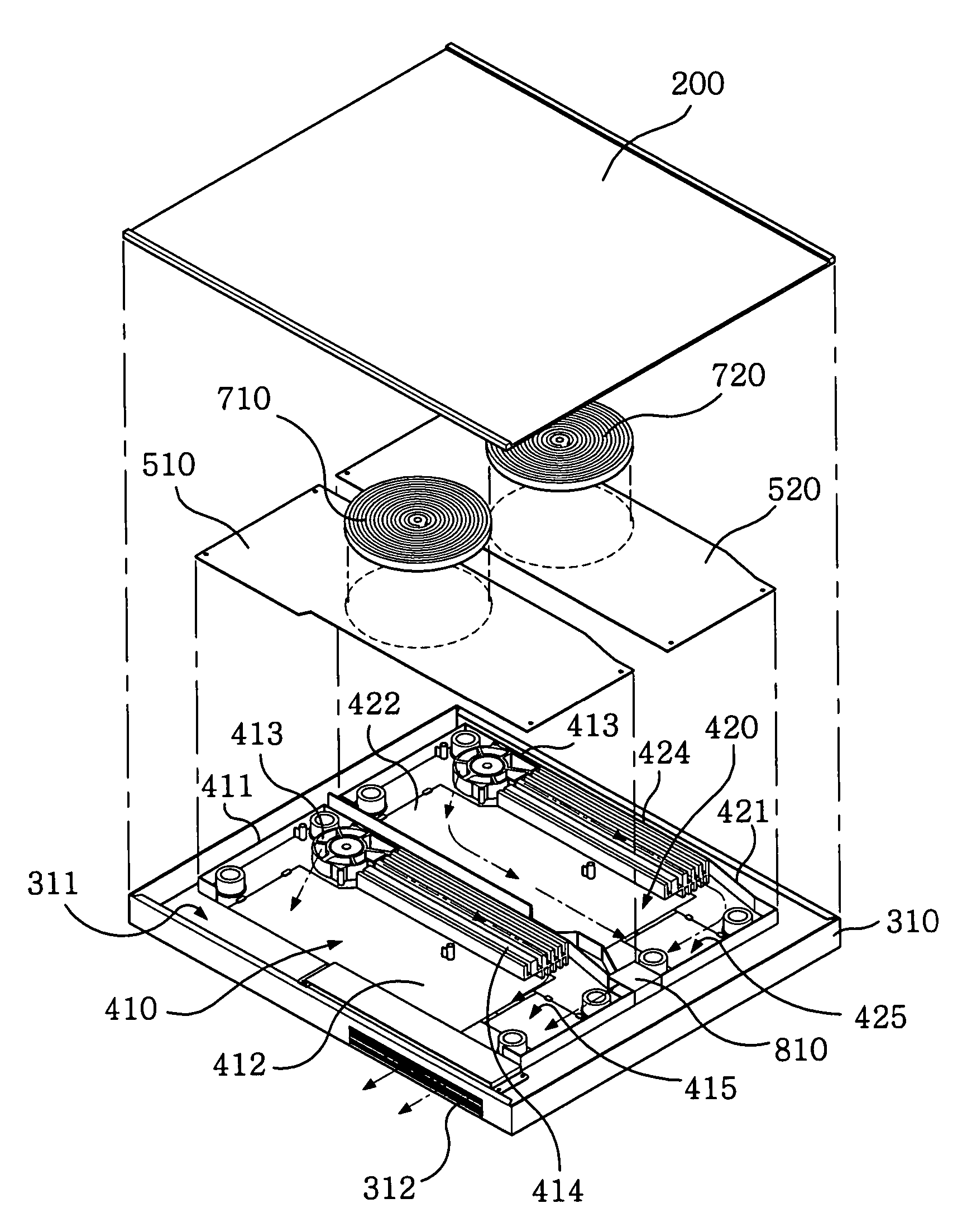
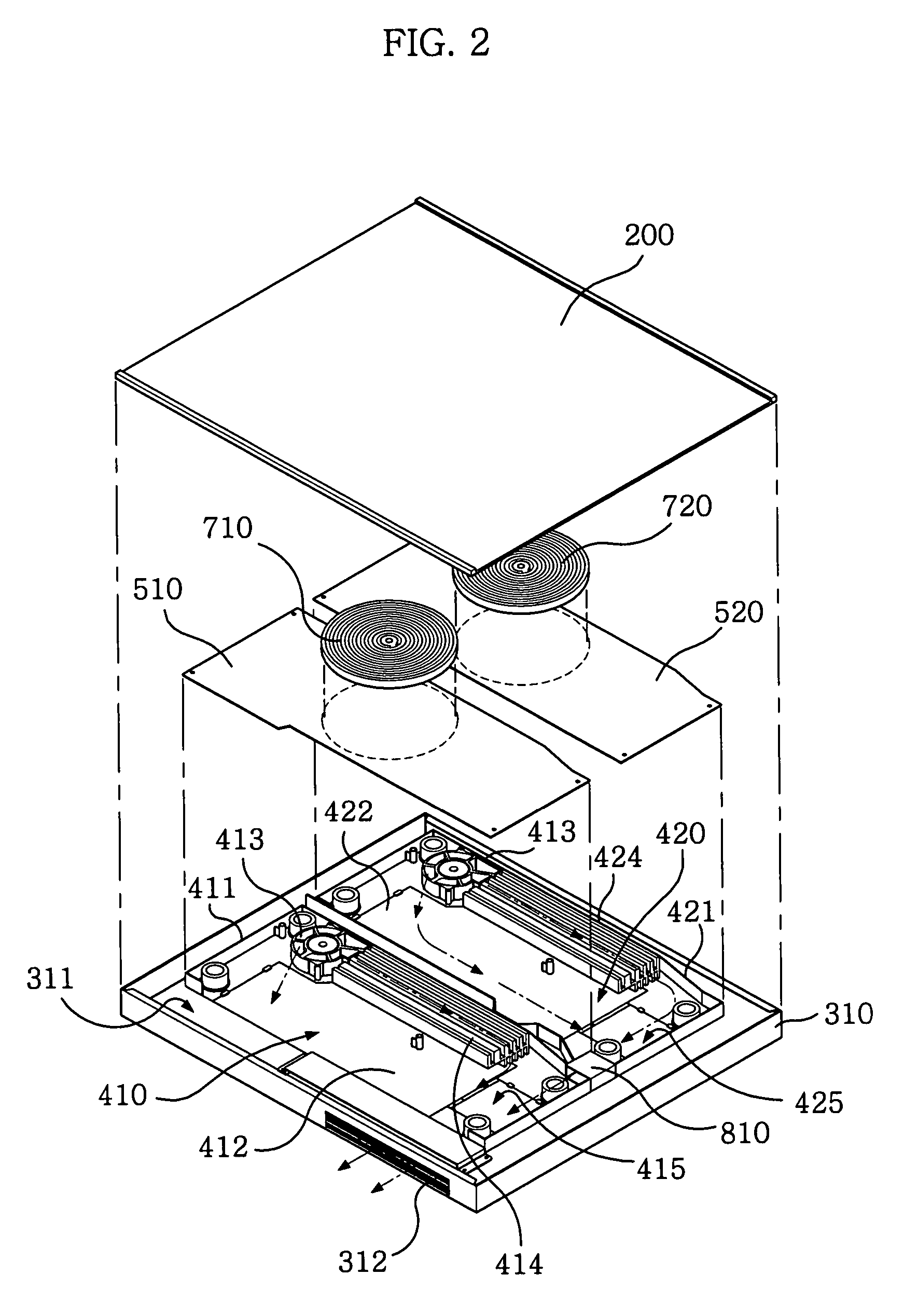
[0024]Referring to FIG. 2, an induction heating cooker of the present invention comprises a cooking plate 200 formed at the uppermost of the cooker on which a metal vessel is seated, a cooking body 310 coupled to the cooking plate 200, and first and second induction heating modules 410 and 420 installed within the cooking body 310. Reference numerals 510 and 520 denote first and second base seats each installed on the top of the unit induction heating modules 410 and 420.

[0025]The cooking plate 200 made of ceramic glass is coupled to the cooking body 310 with a predetermined size of receiving space 311 defined therebetween. An exhaust port 312 through which heated air is discharged to the outside is laterally formed at the cooking body 310.

[0026]The first and second unit induction heating modules 410 and 4...


PUM


Abstract

An induction heating cooker with improved discharge capability and cooling performance comprises a cooking plate 200 formed with a cooking vessel thereon; a cooking body 310 coupled to the cooking plate 200 to define a receiving space 311 therebetween and having an exhaust port 312 communicating with the receiving space 311; a plurality of unit induction heating modules 410 and 420 installed within the receiving space 311 to be partitioned from each other, each having a heating unit 412 or 422, a blowing fan 413 or 423 disposed close to the heating unit to cool the heating unit 412 or 422, and an exhaust passage 415 or 425 for allowing exhaust air generated by the blowing fan 413 or 423 to be guided to and discharged through the exhaust port 312; and a bridge duct 810 for allowing the exhaust passages 415 and 425 of the unit induction heating modules 410 and 420 to communicate with each other, to thereby enable to improve the cooling performance.

Description

BACKGROUND OF THE INVENTION[0001]1. Field of the Invention[0002]The present invention relates to an induction heating cooker for heating food using an electromagnetic induction method. In particular, the invention relates to an induction heating cooker by which discharge capability and cooling performance can be improved.[0003]2. Description of the Related Art[0004]Recently, induction heating cookers employing an induction heating method has gained popularity as a future cooking appliance, because its stability and economical efficiency is excellent as compared with a conventional cooling appliance such as a gas stove. Such an induction heating cooker is a cooking appliance using direct heating method. In such a case, when Alternating Current (AC) is applied to an induction heating coil in an induction oven, a magnetic field is produced to induce an eddy current effect on the bottom of a vessel (e.g., a receptacle containing iron ingredients) placed at the center of the magnetic fie...

Claims


Application Information

Patent Timeline
IPC IPC(8): H05B6/12F24C15/10
CPCH05B6/1263H05B2206/022H05B6/12
Inventor PARK, BYEONG WOOKKIM, JONG SIK
Owner LG ELECTRONICS INC
Why Eureka
Try Eureka