Controlling devices using cascaded control units

Inactive Publication Date: 2006-11-14
POWER INTEGRATIONS INC
View PDF5 Cites 12 Cited by
  • Summary
  • Abstract
  • Description
  • Claims
  • Application Information

AI Technical Summary

Benefits of technology

[0012]One aspect of this invention provides a method of controlling a plurality of controlled devices in a predetermined sequence, comprising the steps of: providing a plurality of control units each comprising a plurality of state machines each for controlling a respective controlled device; allocating the plurality of controlled devices to respective state machines in said plurality of control units whereby the control units are cascaded in accordance with the predetermined sequence, with a single linear path of the predetermined s

Problems solved by technology

For a number of n state machines, this implies a network of n(n−1) signal paths among the state machines, and quickly becomes impractical with increasing n, i.e. an increasing number of

Method used


Image

  • Controlling devices using cascaded control units
  • Controlling devices using cascaded control units
  • Controlling devices using cascaded control units

Examples


Embodiment Construction

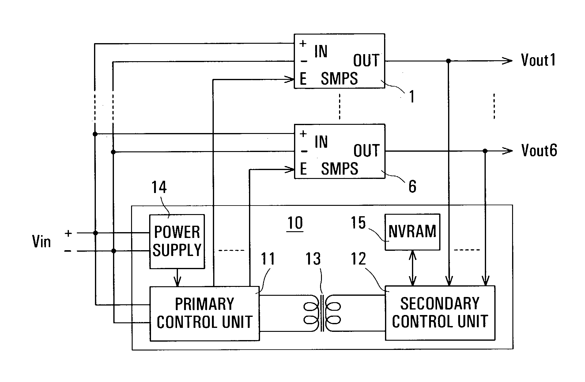
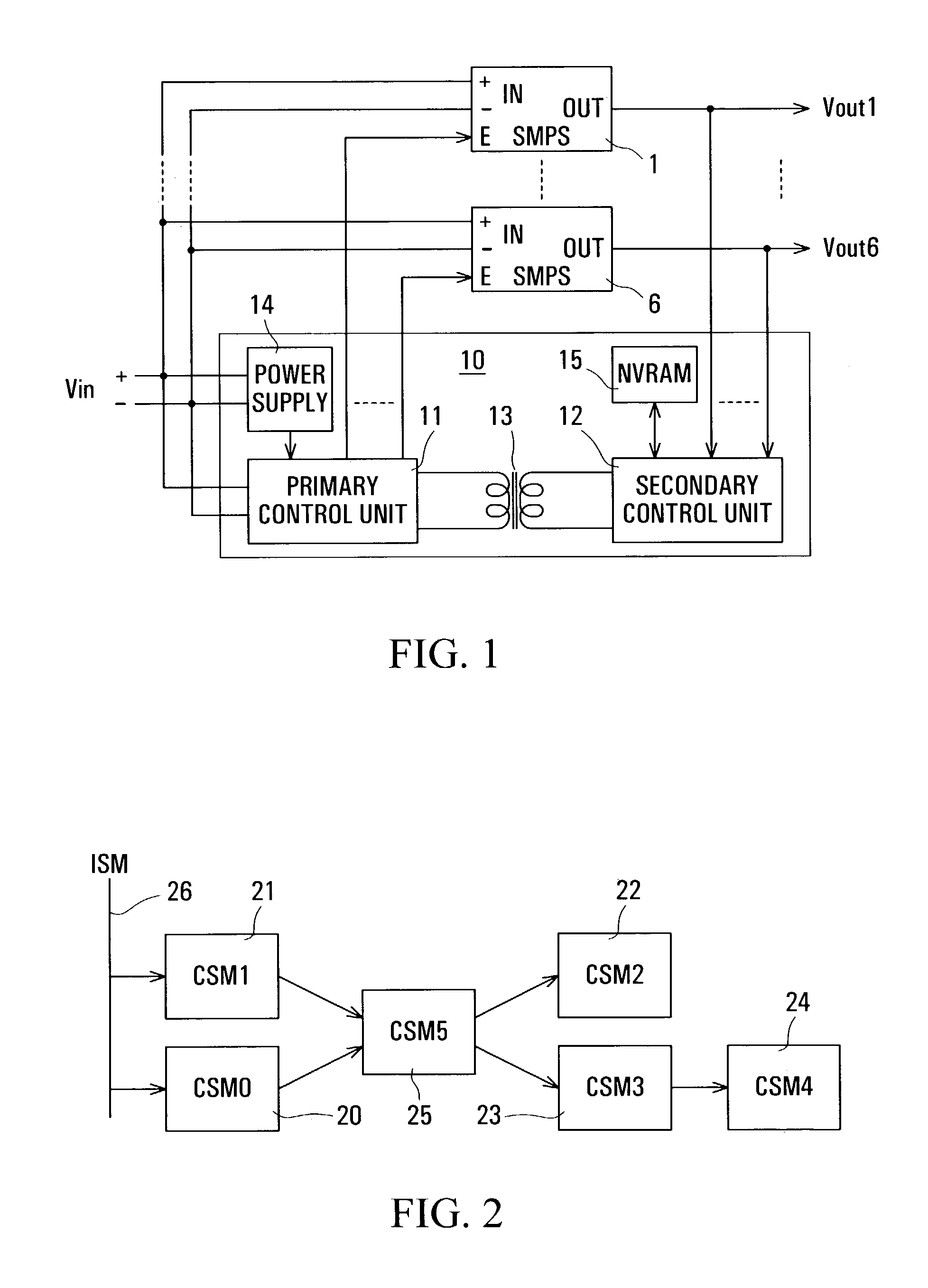
[0031]Referring to FIG. 1, a power supply controller unit (PSCU) 10 is illustrated for controlling a plurality of isolating power supplies, for example up to six power supplies two of which are represented in FIG. 1 by switched mode power supplies (SMPS) 1 and 6, others being indicated by dashed lines. The PSCU 10 comprises two control units 11 and 12, referred to as primary and secondary control units respectively, which are electrically isolated from one another and between which signals are coupled in both directions by a transformer 13. The PSCU 10 also comprises a power supply 14 for the primary control unit 11, and a non-volatile memory (NVRAM) 15 coupled to the secondary control unit 12.

[0032]Each of the power supplies 1, . . . 6 has an enable input E and inputs + and − for a source voltage Vin on its primary side, and an isolated output OUT on its secondary side providing a respective output voltage Vout1, . . . Vout6. These output voltages are monitored by the secondary con...


PUM


Abstract

Power supplies, supplied with an input voltage to produce output voltages, are controlled in a desired sequence, and their output voltages are monitored, by respective state machines of two or more control units which are coupled in cascade by a bidirectional signal path on which commands and acknowledgements are coupled serially in frames. Within each control unit, each state machine communicates with all of the other state machines, so that the power supplies controlled by a single control unit can include divergent and convergent as well as linear sequence paths. The sequence is linear between adjacent control units, with logical combinations of received and locally-produced commands and acknowledgements. An input state machine in the first control unit in the cascade monitors the input voltage to initiate a power-up sequence.

Description

[0001]This invention relates to controlling devices using cascaded control units, and is particulary concerned with signal coupling between cascaded power supply control units for controlling or sequencing power supplies.REFERENCE TO RELATED APPLICATIONS[0002]Reference is directed to the following copending U.S. patent applications, all filed on May 2, 2003, the entire disclosure of each of which is hereby incorporated herein by reference:[0003]“Power Supply Controller”, R. Orr et al., (79115-8, PP010);[0004]“Sequencing Power Supplies”, D. Brown et al., (79115-20, PP011);[0005]“Coupling Signals Via A Coupling Arrangement”, D. Brown et al., (79115-16, PP014).BACKGROUND[0006]The related applications describe and claim a power supply controller, and coupling of signals in such a controller, which can be used for controlling a plurality of isolating power supplies, such as switch mode power supplies or DC power converters and voltage regulators, for providing controlled electrical power...

Claims


Application Information

Patent Timeline
IPC IPC(8): H02J1/00H02J3/00H02J7/00G06F1/26G06F1/32H02M3/28
CPCG06F1/26G06F1/3203H02M3/28
Inventor BOROS, MIRCEA CRISTIANBROWN, DAVID ALAN
Owner POWER INTEGRATIONS INC
Why Eureka
Try Eureka