Method for debugging of process or manufacturing plant solutions comprising multiple sub-systems

a technology of process or manufacturing plant and sub-system, applied in the direction of program control, instruments, safety arrangments, etc., can solve the problems of inability to proof conditions about parameters, signals, actuators or sensors, out of their scope, and no known method or system for system wide debugging across different control sub-systems

Active Publication Date: 2013-08-22
ABB (SCHWEIZ) AG
View PDF17 Cites 17 Cited by
  • Summary
  • Abstract
  • Description
  • Claims
  • Application Information

AI Technical Summary

Problems solved by technology

However, there is no known system or method for debugging a complex control system across different control systems, different domains, different field buses, different field devices and different distributed control systems (DCS), programmable logic controller (PLC) or supervisory control and data acquisition (SCADA) systems, even in combination with plant simulators, device simulators or control simulators.
But since the engineering data is distributed to different engineering tools, there is no known method or system for a system wide debugging across different control sub-systems, which usually contain different types of control equipment.
Once the process is started during FAT or commissioning, the sub-system specific engineering tools cannot proof conditions about parameters, signals, actuators or sensors, which are out of their scope.
Additionally, there is no known technical method or system known, which allows stopping control code execution of multiple control devices, which may be of different types of control equipment, neither in a virtual test environment nor in the real plant, at the same time in conjunction with the process including a number of devices which provide control functionalities.
Resulting, it is hard to get test and debugging results at a glance.
Although a simulation enables imm

Method used


Image

  • Method for debugging of process or manufacturing plant solutions comprising multiple sub-systems
  • Method for debugging of process or manufacturing plant solutions comprising multiple sub-systems
  • Method for debugging of process or manufacturing plant solutions comprising multiple sub-systems

Examples


Embodiment Construction

[0026]Exemplary embodiments of the present disclosure provide a plant debugger for the control system and the corresponding industrial process at hand, according to the initial part of the present disclosure which overcomes the mentioned issues and deficiencies and provides a domain independent plant debugger across multiple sub-systems and different sub-system types.

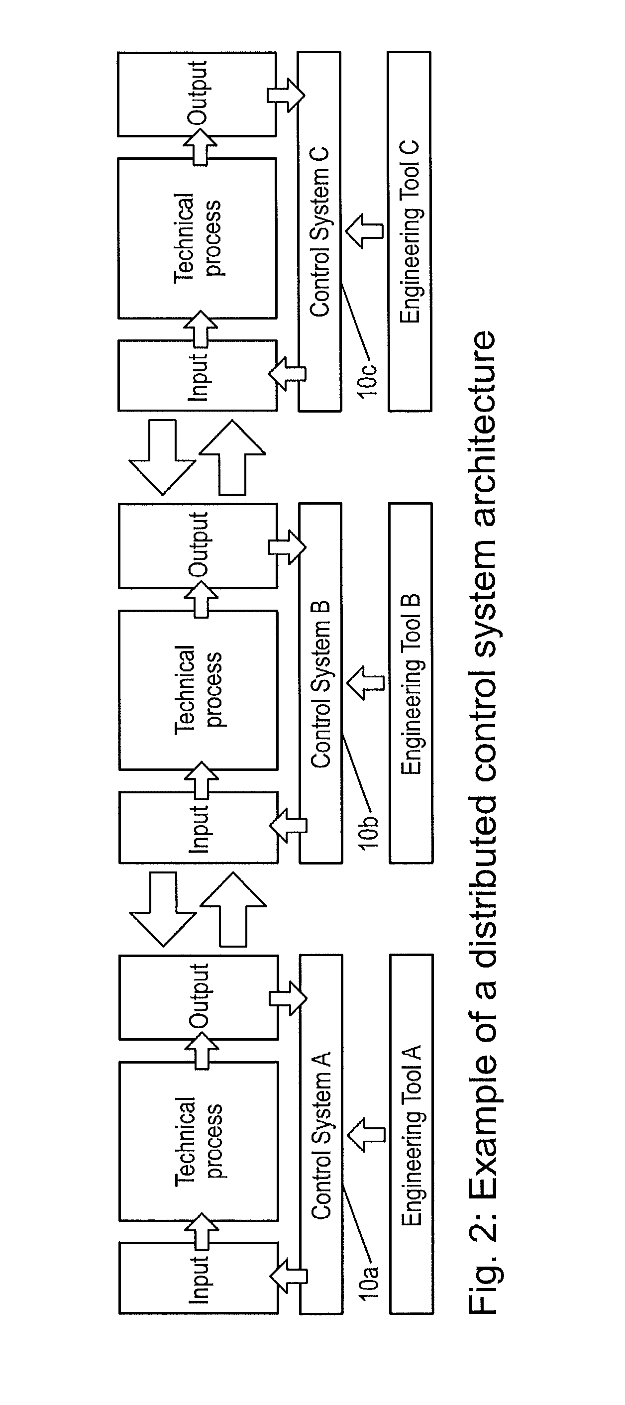
[0027]The plant debugger can start and stop multiple control systems and / or the corresponding process or simulation models of them from a single point of access in a synchronized and / or non-synchronized mode.

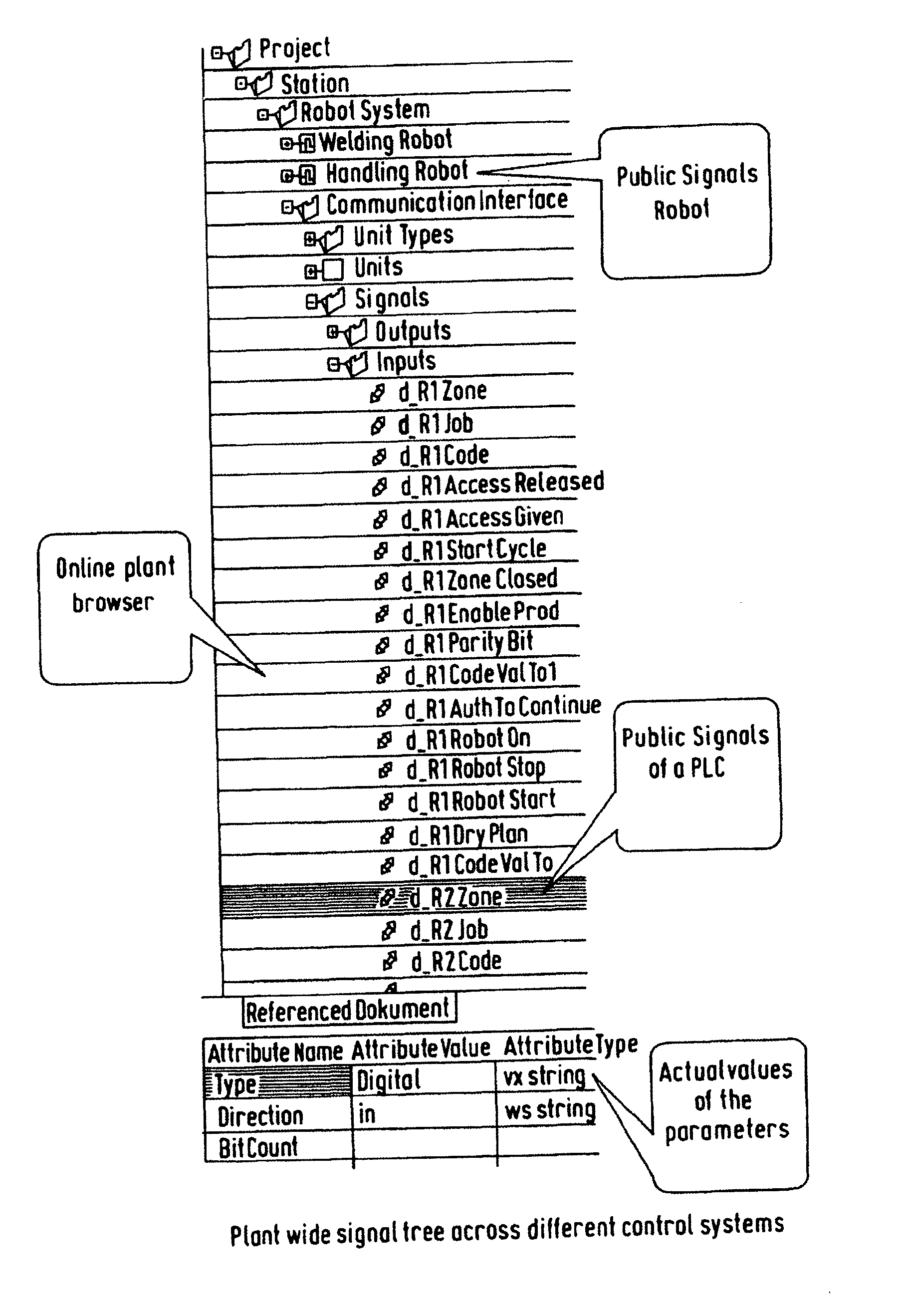
[0028]Hence, the exemplary embodiments characterized in that said plant debugger system, which can be a software tool or a device or a device running software, provides all available signals of all corresponding control sub-systems, of different or same control equipment types, within a single sight. This sight provides the signals to the user, which are publicly available during engineering, commissioning and FAT.

[...


PUM


Abstract

An exemplary method and a system for debugging a control system of an industrial plant where the system includes at least two different control sub-systems, of the same or different control equipment type, on plant or sub-system level, and has specific programmable controller units in devices like PLCs, DCSs, robots, drives, instruments and/or other process specific components whereas all specified parameters and signals of the control system across its sub-systems, devices, and technologies are extracted and visualized on a single sight and are utilized for the definition of system wide breakpoints, utilizing a subset of those signals or parameters, and related conditions, e.g. logical combinations of the signals or parameters.

Description

RELATED APPLICATION(S)[0001]This application is a continuation under 35 U.S.C. §120 of International Application PCT / EP2010 / 005343 filed on Aug. 31, 2010 and designating the U.S., the entire content of which is hereby incorporated by reference in its entirety.FIELD[0002]The disclosure relates to a method and system for debugging on a plant or sub-system level, such as debugging a control system including the corresponding process, e.g. a factory cell, a factory line, a process plant, a mechatronical unit, a machine or a complete plant.BACKGROUND INFORMATION[0003]Known control systems are largely used with the purpose of controlling industrial processes. However, there is no known system or method for debugging a complex control system across different control systems, different domains, different field buses, different field devices and different distributed control systems (DCS), programmable logic controller (PLC) or supervisory control and data acquisition (SCADA) systems, even i...

Claims


Application Information

Patent Timeline
IPC IPC(8): G05B9/02
CPCG05B17/02G05B19/0426G05B19/056G05B9/02G05B2219/13142G05B2219/23283G05B2219/33297G05B2219/13037
Inventor HOERNICKE, MARIODRATH, RAINERSCHROETER, BENLANGER, KURTLALU, JARKKO
Owner ABB (SCHWEIZ) AG
Why Eureka
Try Eureka