Modular electrical harness for jet aircraft landing gear systems

a module and electrical harness technology, applied in the direction of insulated conductors, cables, conductors, etc., can solve the problems of erroneous readings and interpretations, certain regional jet operators to miss and/or cancel flights, electrical failures in the landing gear anti-skid system, etc., to achieve quick and easy troubleshooting and replacement of certain sections of the harness, and reliable products. , the effect of facilitating the maintenan

Inactive Publication Date: 2006-11-14
FONDRIEST WILLIAM
View PDF11 Cites 10 Cited by
  • Summary
  • Abstract
  • Description
  • Claims
  • Application Information

AI Technical Summary

Benefits of technology

[0018]The present invention is directed to a modular landing gear harness to be used on a regional jet aircraft. The harness is designed to allow the aircraft technicians the ability to troubleshoot and replace certain sections of a harness quicker and easier than previously allowed. More specifically, the present invention not only makes a harness a more reliable product through its inherent design, but also allows an aircraft technician the ability to remove and replace a specific portion of a harness without disrupting the other systems associated with a harness. The quick nature in which a harness can be diagnosed and a specific section can be replaces allows for quicker turn around of aircraft and less cancellations.

Problems solved by technology

One of the major problems causing certain regional jet operators to miss and / or cancel flights was electrical failures in the landing gear anti-skid system.
A failure in the harness sends false signals which can cause erroneous readings and interpretations.
These false readings and interpretations can cause flights to be cancelled and lengthy troubleshooting efforts to identify and repair the problem.
Extensive research found that a landing gear anti-skid harness had several flaws that contributed to the failures and / or to the lengthy troubleshooting and repair efforts.
The first problem with a harness was that it had no feature to prevent the contamination of a harness by dirt and / or liquids.
The second, and more important problem, was that when troubleshooting a harness, because of its design nature, it was impossible to remove and replace a single portion of a harness, without disrupting the entire harness.
This usually meant that the aircraft would have to be removed from the gate and returned to the hangar for extensive troubleshooting and maintenance.
Flights were cancelled and revenue was lost when this problem occurred.
Once the problem with a harness was found, which usually was attributed to a failure of the anti-skid portion due to moisture ingress, the entire harness would have to be replaced.
Since the complete harness assembly would have to be removed and replaced, additional harness assemblies would have to be maintained in stock, at different locations, which would add additional inventory and cost burden to the carrier.
This would mean that its total usage for that day would have to be cancelled and if another aircraft was not put into service to cover its original flight cancellation, then additional flights within the system would be adversely effected.
This would cause loss revenue and customer dissatisfaction which could have catastrophic consequences in the long term.
In addition, is has been found that certain portions of prior art harnesses were burdened with significant limitations.
More particularly, it has been found that prior art harnesses, and particularly the upper main sub-assembly failed after, and mostly as a result of, repeated retraction and extension of the landing gear.
Failure of the main sub-assembly may result in exposure and / or damage of the internal wires.

Method used


Image

  • Modular electrical harness for jet aircraft landing gear systems
  • Modular electrical harness for jet aircraft landing gear systems
  • Modular electrical harness for jet aircraft landing gear systems

Examples


Embodiment Construction

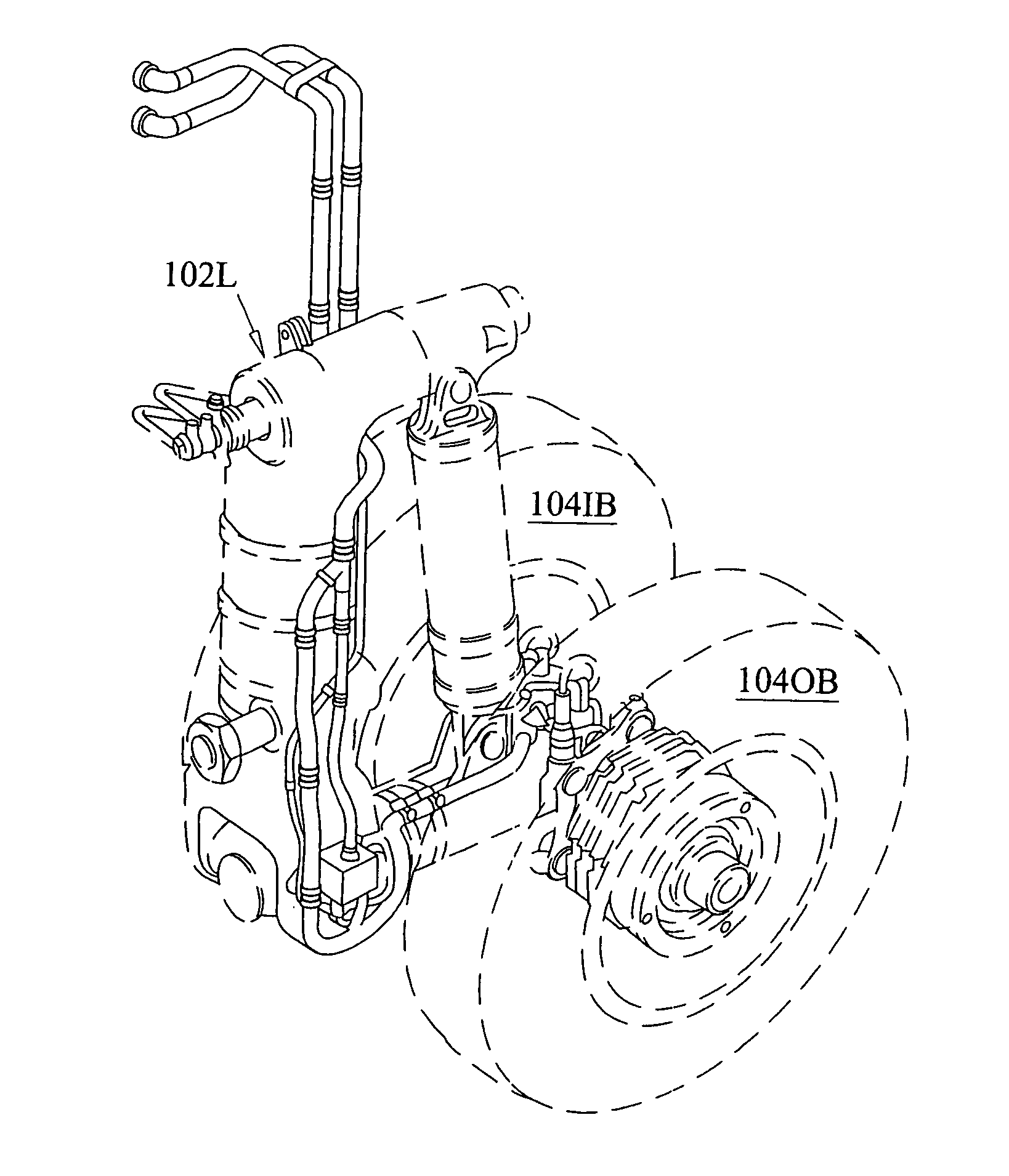
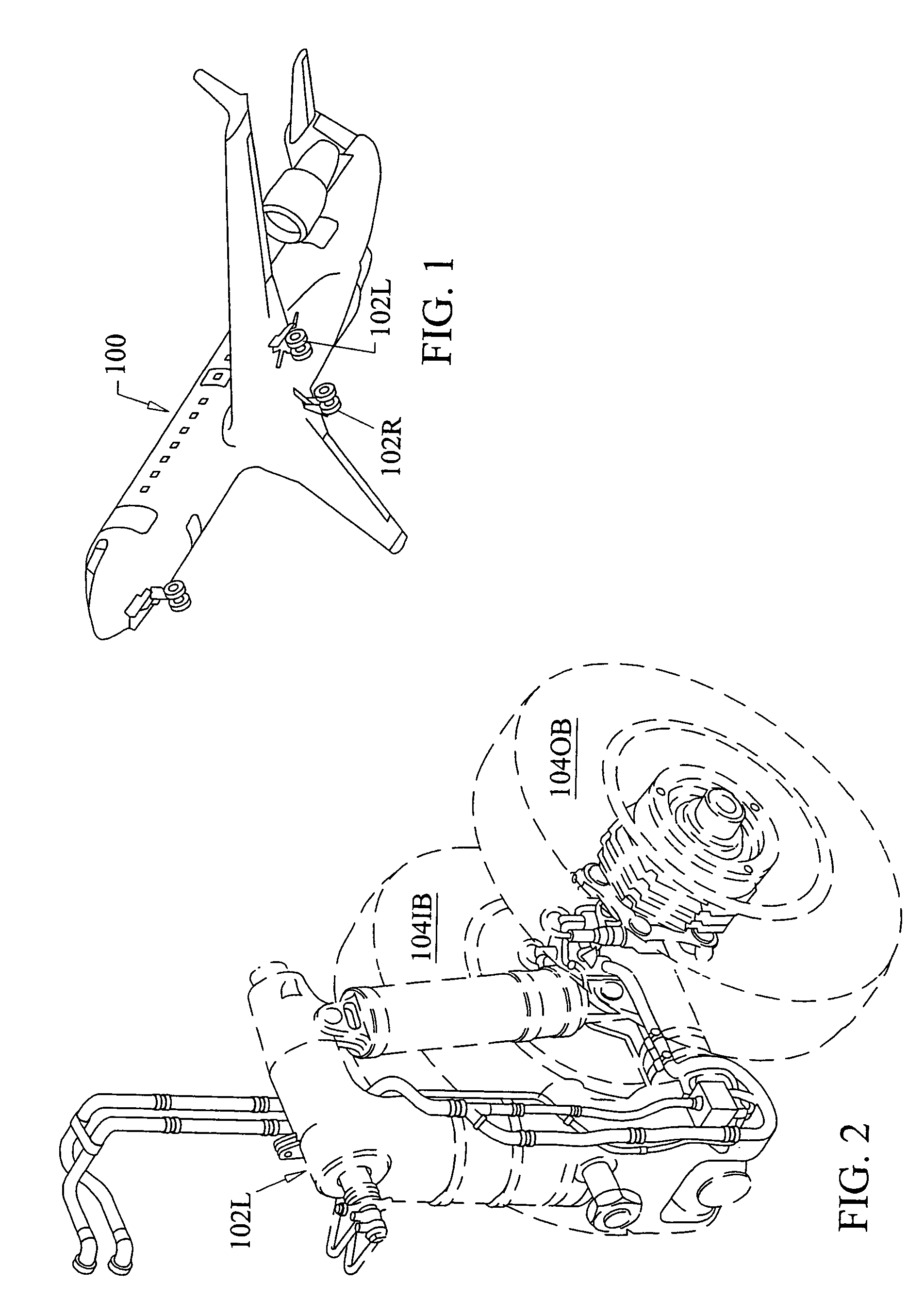
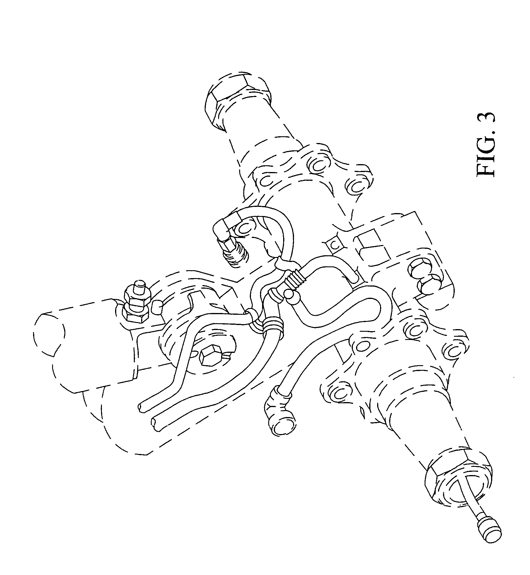
[0035]With reference now to the drawings, as best the present invention provides an electrical wiring harness specifically designed for use on the main landing gear of a jet aircraft as best illustrated in FIGS. 1–5. More particularly, a modern jet aircraft, such as the CANADAIR Regional Jet referenced as 100, includes left and right main landing gear systems, referenced as 102-L and 102-R respectively. FIG. 2 is a partial view of the left main landing gear 102L and depicts the landing gear in a partially deployed configuration. FIG. 3 is a partial detailed view of the lower portion of the main landing gear with the wheels removed. FIGS. 4 and 5 depict inboard side views of the left and right main landing gear in fully deployed (e.g. down) configuration with the wheels removed.

[0036]Each left and right main landing gear system, 102-L and 102-R, have inboard and outboard wheels, referenced as 104-IB and 104-OB respectively. Each of the wheels includes a brake temperature sensing syst...


PUM

PropertyMeasurementUnit
weightaaaaaaaaaa
corrosion resistanceaaaaaaaaaa
abrasion resistantaaaaaaaaaa

Abstract

An improved modular landing gear harness for use on a jet aircraft is disclosed. The modular landing gear harness is divided into four sub-assemblies including the main sub-assembly, the brake temperature monitoring sub-assembly, the weight off wheels sub-assembly, and the anti-skid sub-assembly. The various sub-assemblies may be connected to form a unitary harness that provides a protective conduit for wiring for critical landing gear systems. The use of light-weight composite connectors facilitates troubleshooting and substantially reduces the overall weight of the harness assembly.

Description

CROSS REFERENCE TO RELATED APPLICATIONS[0001]N / ASTATEMENT REGARDING FEDERALLY SPONSORED RESEARCH OR DEVELOPMENT[0002]N / ACOPYRIGHT NOTICE[0003]A portion of the disclosure of this patent document contains material that is subject to copyright protection. The copyright owner has no objection to the facsimile reproduction by anyone of the patent document or patent disclosure as it appears in the Patent and Trademark Office patent file or records, but otherwise reserves all copyrights rights whatsoever.BACKGROUND OF THE INVENTION[0004]1. Field of the Invention[0005]The present invention relates to electrical systems for jet aircraft, and more particularly to a modular electrical harness assembly for use on the main landing gear of a jet aircraft.[0006]2. Description of the Background Art[0007]The aviation industry is generally divided into two major providers, major air carriers and regional air carriers. The major carriers are those who operate larger jet aircraft that are capable of tr...

Claims


Application Information

Patent Timeline
Patent Type & Authority Patents(United States)
IPC IPC(8): H01B7/30B60L1/00B60L3/00
CPCB64C25/36H02G3/0481
Inventor FONDRIEST, WILLIAM
Owner FONDRIEST WILLIAM
Why Eureka
Try Eureka