Surface mount crystal oscillator

a surface mount, quartz crystal technology, applied in the direction of oscillator, piezoelectric/electrostrictive/magnetostrictive device, piezoelectric/electrostrictive/magnetostriction machine, etc., can solve the problem of large outer dimensions inhibit the reduction in the difficulty in reducing the size of the crystal oscillator, etc. problem, to achieve the effect of satisfying the vibration

Inactive Publication Date: 2006-11-14
NIHON DEMPA KOGYO CO LTD
View PDF9 Cites 50 Cited by
  • Summary
  • Abstract
  • Description
  • Claims
  • Application Information

AI Technical Summary

Benefits of technology

[0013]It is therefore an object of the present invention to provide a surface mount crystal oscillator which facilitates a reduction in size thereof.
[0016]With the employment of the crystal blank having the extending electrodes extended to both sides on one edge thereof, the crystal blank securely cantilevered, thereby maintaining satisfactory vibration characteristics of the crystal blank.
[0017]In the present invention, the crystal oscillator can preferably employ the insulator which is a insulator substrate on which a pair of crystal terminals are disposed corresponding to the positions at which the pair of extending electrodes are formed. The crystal terminals thus disposed can further ensure the electric connection of the conduction terminals to the crystal blank.
[0018]In the present invention, since the crystal blank is placed on the insulator disposed on the IC chip, it is not necessary to form a step in the package body to secure the crystal blank to the step. Consequently, the crystal oscillator can be reduced in outer planar dimensions, thus facilitating a reduction in size of surface-mount type crystal oscillators.

Problems solved by technology

In the foregoing crystal oscillator, however, crystal blank 3 has one end held on one step within the recess of package body 1, and the other end carried on the other step, so that the resulting crystal oscillator has a problem of large outer dimensions.
Actually, slow progress of reduction in size of IC chip 2 eventually results in difficulties in reduction in size of a crystal oscillator.
However, even in the structure illustrated in FIG. 2, a step required for disposing the crystal terminals causes the crystal oscillator to have an outer planar size much larger than the size of IC chip 2, thus inhibiting the reduction in size of the crystal oscillator.

Method used


Image

  • Surface mount crystal oscillator
  • Surface mount crystal oscillator
  • Surface mount crystal oscillator

Examples


Embodiment Construction

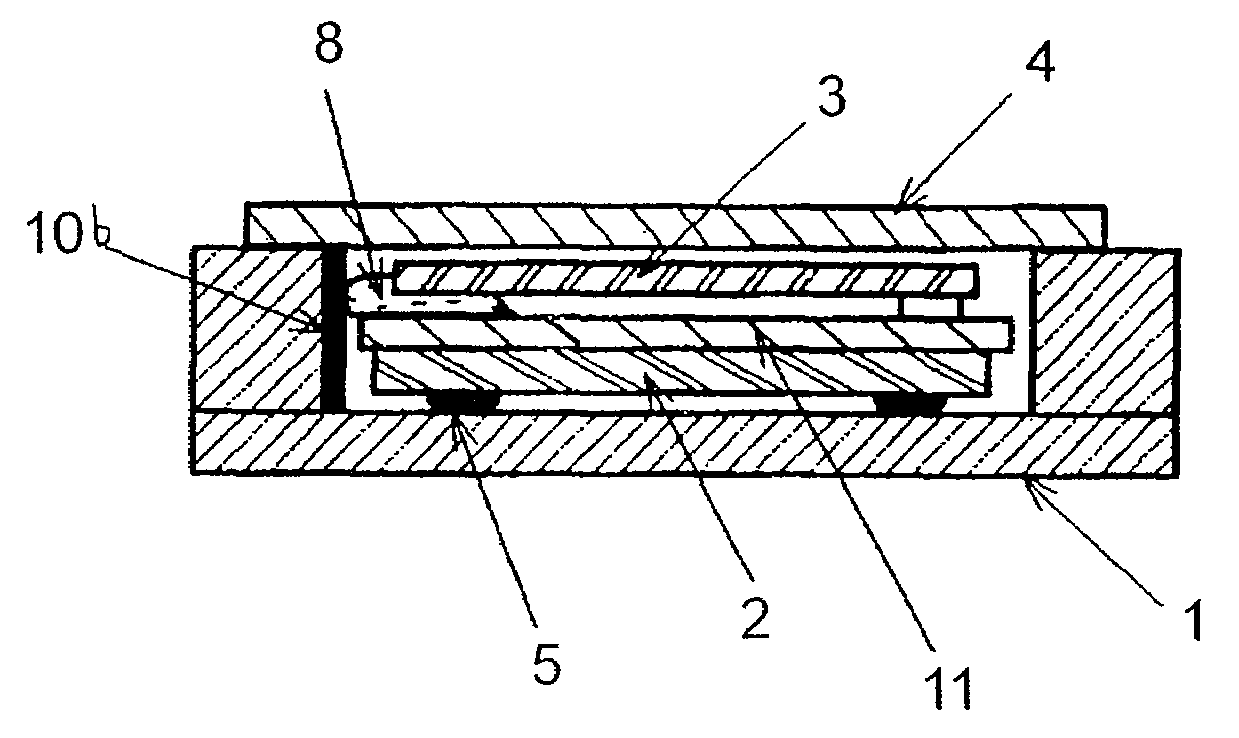
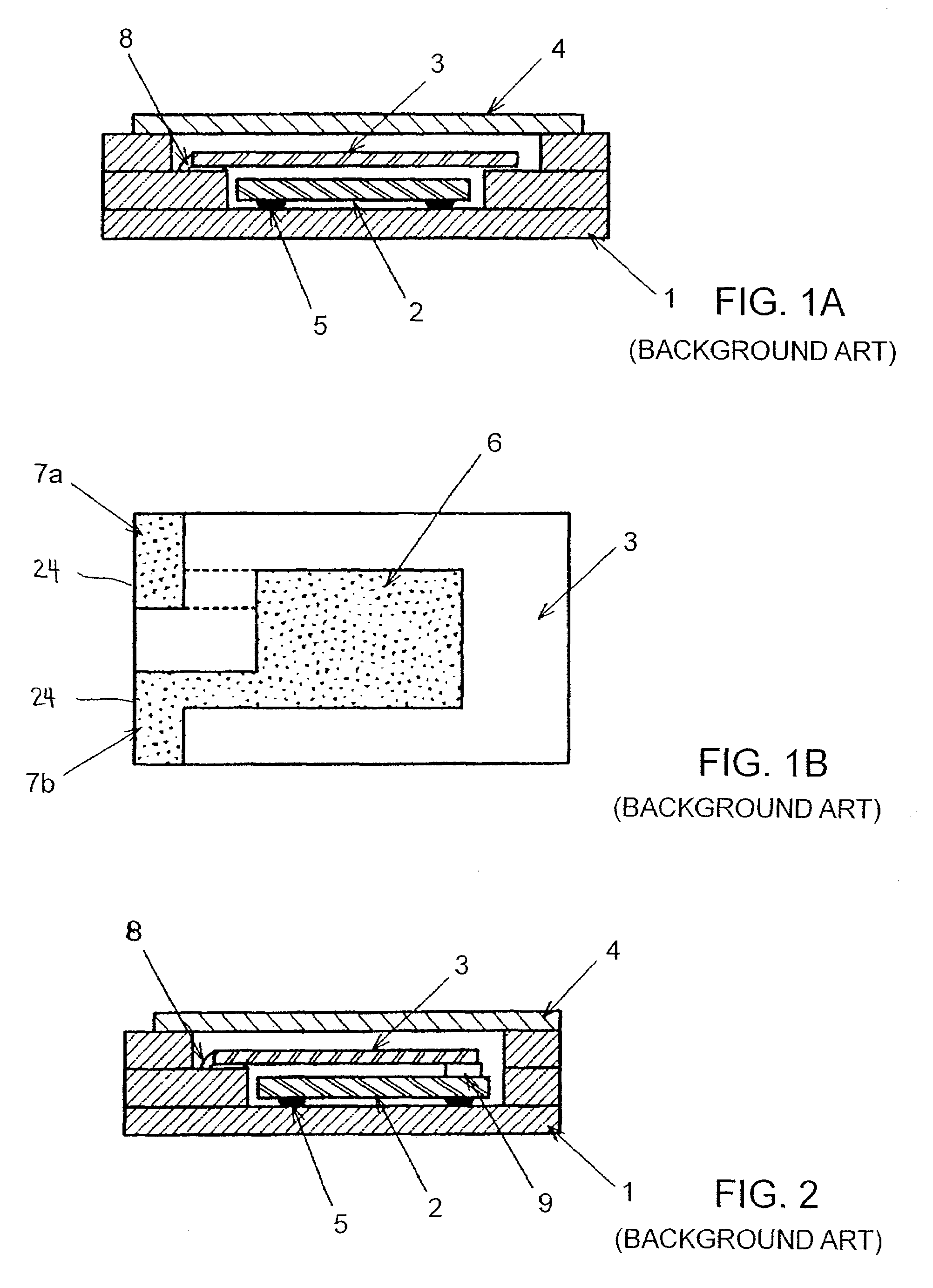
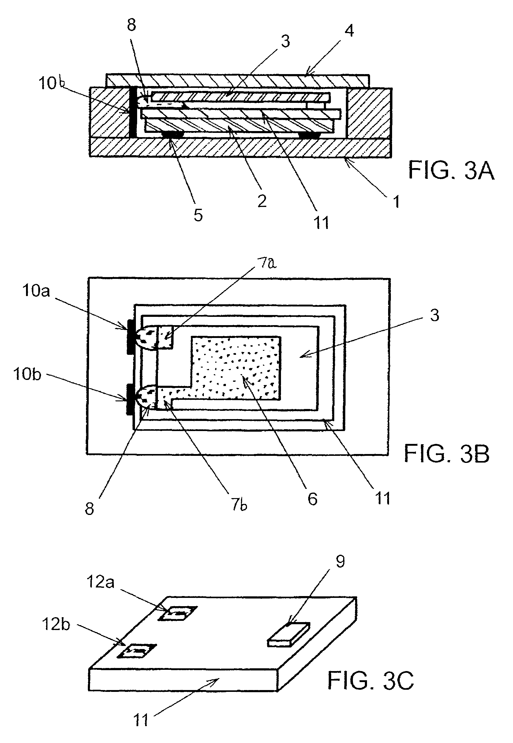
[0027]In FIGS. 3A to 3C which illustrate a surface mount crystal oscillator according to one embodiment of the present invention, components identical to those in FIG. 1A are designated the same reference numerals, so that repetitive discussions are simplified or omitted in the following description.

[0028]As described above, the surface mount quartz crystal oscillator illustrated in FIGS. 3A to 3C comprises package body 1 having a recess; IC (integrated circuit) chip 2 having an oscillator circuit integrated therein; crystal blank 3 (see FIG. 1B) having extending electrodes 7a, 7b extending from both ends of one edge thereof; and cover 4 for enclosing the recess. IC chip 2 and crystal blank 3 are contained in the recess of package body 1, and cover 4 is placed over the recess to hermetically encapsulate IC chip 2 and crystal blank 3 within package body 1. Unlike the crystal oscillator illustrated in FIG. 1A, the crystal oscillator of the present embodiment is not formed with any ste...


PUM


Abstract

A surface mount quartz crystal oscillator comprises a package body having a recess, a quartz crystal blank having extending electrodes extending from the outer periphery of the crystal blank, an IC (integrated circuit) chip secured to an inner bottom surface of the recess and having at least an oscillator circuit connected to the crystal blank, and an insulator disposed on the IC chip. A pair of conduction terminals are disposed on an inner wall surface of the recess and electrically connected to the IC chip. The crystal blank is secured to the insulator with a conductive adhesive at positions from which the extending electrodes are extended, and the conductive adhesive electrically connects each extending electrode to one conduction terminal associated therewith.

Description

BACKGROUND OF THE INVENTION[0001]1. Field of the Invention[0002]The present invention relates to a surface mount quartz crystal oscillator, and more particularly, to a surface mount crystal oscillator which facilitates a reduction in size.[0003]2. Description of the Related Art[0004]A surface mount crystal oscillator which accommodates a quartz crystal unit and an oscillator circuit using the crystal unit in a surface mount package has been widely used, particularly for portable electronic devices as a frequency or a time reference source because of its small size and light weight. In recent years, an increasing reduction in size has been rapidly advanced in a variety of portable devices represented by portable telephones, causing an associated reduction in size of surface mount crystal oscillators.[0005]A conventional surface mount crystal oscillator illustrated in FIG. 1A employs package body 1 formed with a recess which receives IC (integrated circuit) chip 2 and quartz crystal b...

Claims


Application Information

Patent Timeline
Patent Type & Authority Patents(United States)
IPC IPC(8): H01L41/053H03B5/32H01L41/08H03H9/02H03H9/05H03H9/10
CPCH03H9/0552H03H9/1021
Inventor OKAJIMA, YUKIHIRO
Owner NIHON DEMPA KOGYO CO LTD
Why Eureka
Try Eureka